I decided to go ahead as I first planned and continue with mounting more lights. Even though, as I look back at the last post, I didn’t really install any actual lights yet.
Just so you don’t have to go “way” back to the first post when I actually built them, I am going to be mounting these lights into the dome.

The front and rear logic displays, and the front and rear PSI’s (Process State Indicator). I still have not found a definitive answer of what the “in universe” function of these lights are. The closest I have got is that the PSI basically indicates if the droid is “alive” or not and for the Logic Displays, in The Phantom Menace, it appears that Captain Panaka looks down to the front logic when asked the droids name, by Queen Amidala.
For no particular reason I decided to build and mount the PSI’s first. So I had to turn this,

into something that will look like this.

And mount it to the inside of a dome.
Fortunately, or by design, I’m not sure which. The circuit board fits almost perfectly into a 1 1/2 PVC coupling.

It even has a little ridge to hold the lights in place.
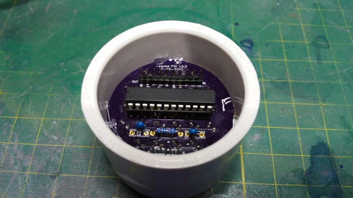
I used a little bit of hot glue to secure it.
Next up I needed to construct some type of diffuser. I looked at two different options.
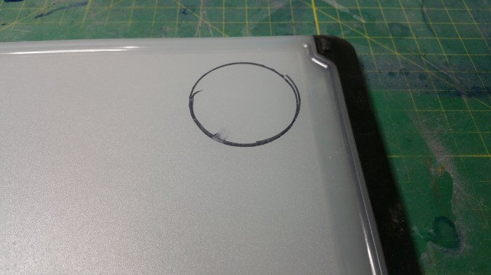
An opaque plastic cutting board.
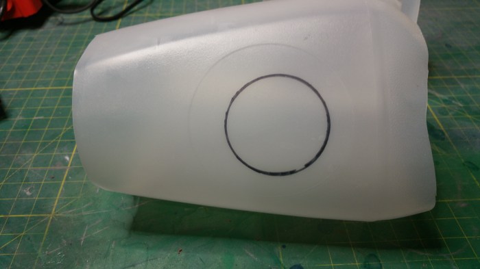
Or a milk jug.
I decided that the cutting board was just too thick for the look I was going for, plus it would have been more difficult to work with.
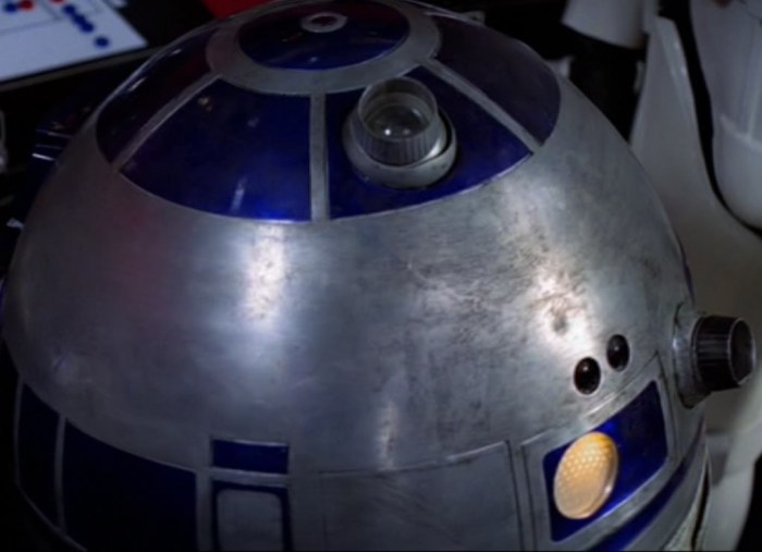
In the picture of R2, that there is also a slight honeycomb pattern in the diffuser as well.
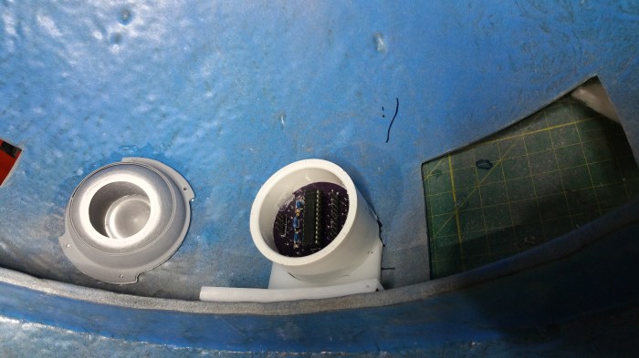
You can see it here on the rear PSI as well.
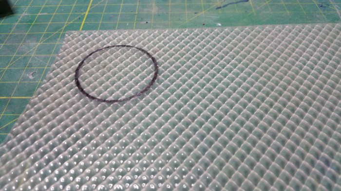
I found a broken Fluorescent light diffuser at work and used that. While not honeycomb, it worked out pretty well.

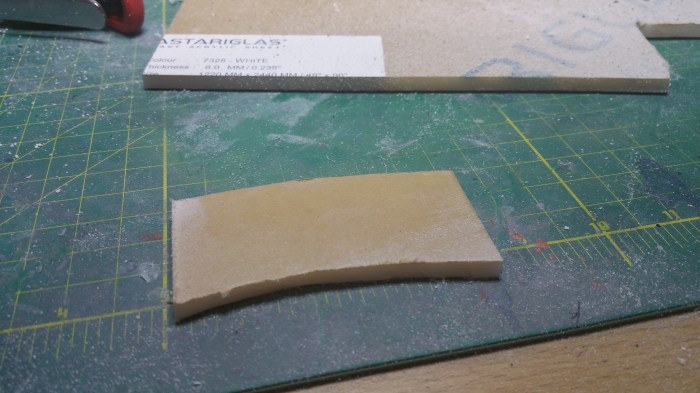
cutting it down to size
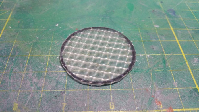
Rounded it off with a dremel.
First I tried it without the other diffuser

I think that the pattern look a little bit too defined. As compared to the actual droid.

I think that looks a lot closer.
I ran into a bit of an issue at this point. I had planned on just gluing these one on top of the other and then just gluing them both into the housing. the problem is there is no real good way to glue both of these to the inside of the housing like this. The glue would pretty much always be visible especially when you shine light through it. On to plan two.
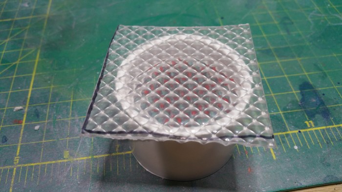
Go oversize. This works out pretty well because one side of the diffuser is not flat, it has ridges which create the pattern you see on the flat side. This allowed the glue to flow in between the diffuser and the rim of the housing.


First I tried clamping it down using a scrap piece, but it did not work out so well. the diffuser ended up bowing from the uneven pressure. So time to resort to an old standby.

The water bottle is back. Here, holding down both front and back housings.

24 hours later, repeat earlier process. Cut off corners
Round off with dremel.

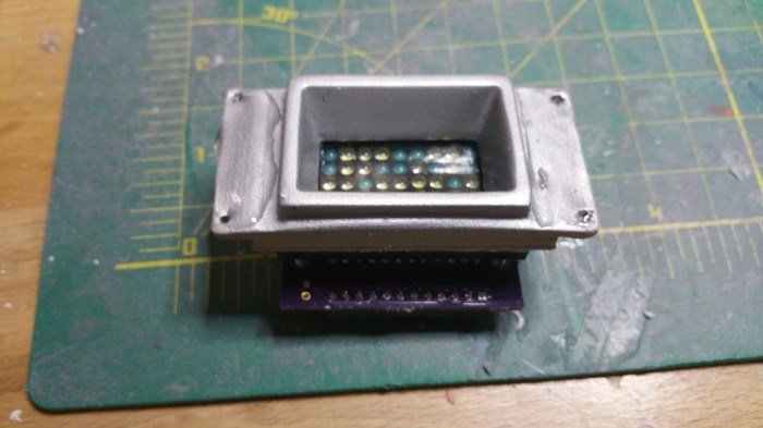
Time to glue on the milk jug diffuser. I ran into another problem at this point. The problem being was that no matter what I tried, the glue would not dry in an even pattern between the milk jug part and the fluorescent diffuser part. If you have ever tried to put a screen protector on your phone or tablet, it was very similar to that except the air bubbles just would not work out. The only solution that I could come up with was to put the milk jug between the LED lights and the fluorescent diffuser. It would not look quite the same, but there was really nothing else i could think of.

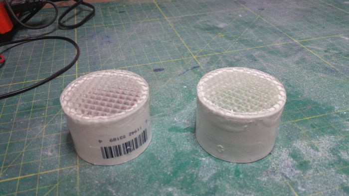
Instead of taking the diffuser off the front I just took the circuit board off the back of the housing and placed the milk jug part, loose, on the other side of the ridge. Maybe not the best solution, but until I can come up with something better it will have to do.

Not bad. Like I said, the pattern is a bit more defined with the milk diffuser in back, but it’s not terrible.
Now I have to figure out how to mount these onto the inside of a dome.
Here I ran into a challenge with the type of dome I decide to use. There are two general types of domes, each can be made of many different types of materials.
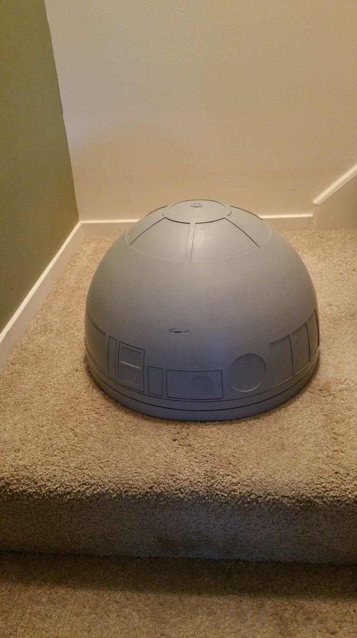
The first type is the single piece dome, like the one I have

The second, and much more popular, type is the two (or multi) part dome.
One of the nice things with a two part dome is you can mount parts to the inside of the smaller dome with screws or captive studs and then place the larger dome on top of that to cover up any holes or screw heads.
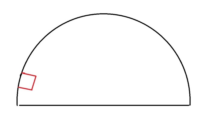
This is basically the issue I was dealing with. How do I mount the red box (PSI) to the inside of the dome if i can’t screw through the dome to mount brackets, and glue won’t work because of too much weight/leverage.
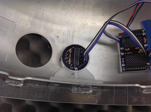
After searching the message board I came across a post which a member was asking for pictures of how people had mounted their electronics inside the dome. A member by the name of “wingspan” posted a picture of a solution he had come up with. He mounted a bracket to a part of the dome that runs completely around the inside of the dome just an inch or so from the bottom.
Really the best picture of the one in my dome up to this point.
It server two main functions. One as a strength member that reinforces the dome. The second, it is a mounting point for the bearing that is used for rotating the dome when mounted to the body.
It had never even crossed my mind to mount a bracket to this “shelf”.
They look relatively easy to construct as well.
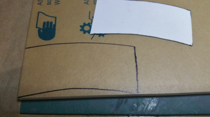
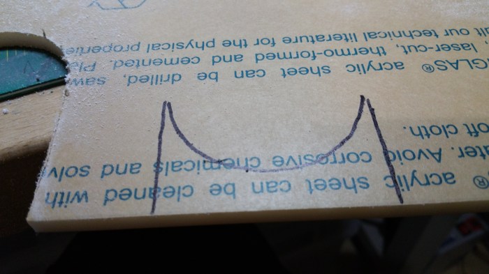
The first thing I did was cut out some paper templates for the rear PSI
The base
The first housing support upright.
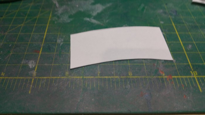
Transferring to the sheet of plastic
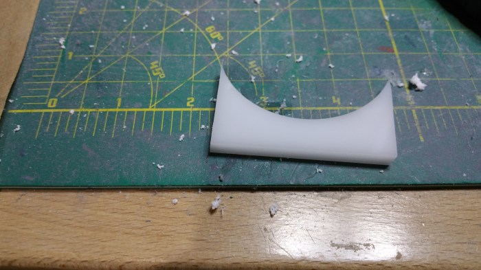
First piece done.

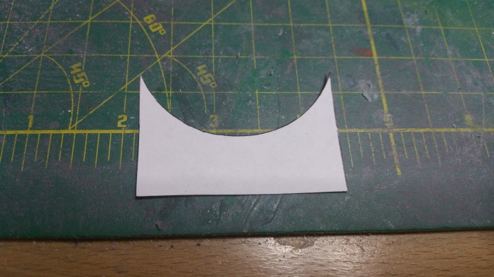
Second piece cut.

Glued together.
Test fit, and determining the height of the second housing upright support.
Marking it out
Third piece cut
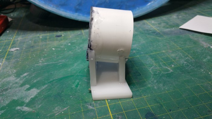
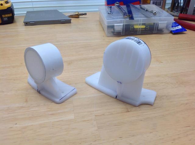
Completed rear bracket/PSI housing.
Basically did the same for the front PSI, the only difference between the two is the height.

Front bracket/PSI housing

Drilled holes so that I can bolt down the brackets

I then chamfered the holes so that the bolt heads will sit flush against the ring, this will ensure that the bearing will sit flat whenever it is installed.

Like this
Now on to the Logics. Fortunately I won’t have to make any brackets for these because I already have some 3d printed bezels that get mounted to them and then they actually go through the dome.
I can’t seem to find any pictures of me prepping/sanding the bezels, but it pretty much the exact same process as the other 3d printed parts I have done already. There is a picture of me painting them in the last post when I painted the holoprojectors.

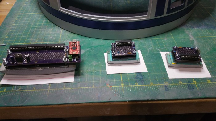
Here are the logics and corresponding bezels.

Pretty easy on these, just apply some glue
Turn upside down to apply pressure, wait 24 hours
Apply glue to other side
These are actually tight enough that I didn’t need lamps.

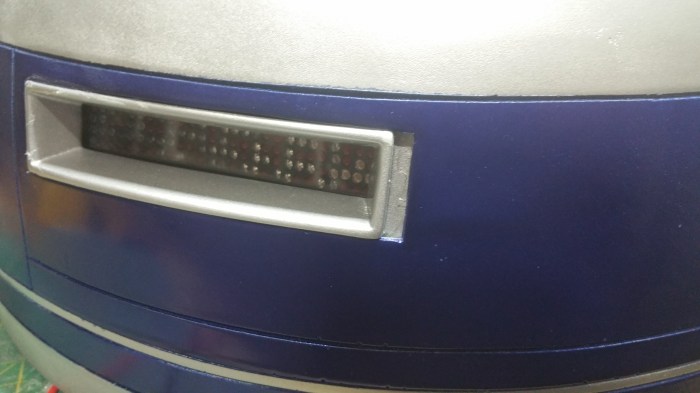
And here is a shot of the front PSI.
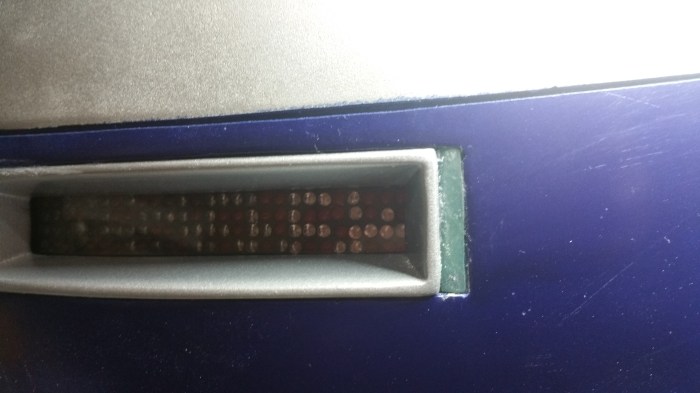
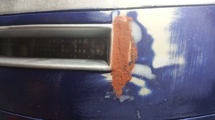
The rear logic had a bit of an issue.
I thought for sure that for some reason I had cut the opening too wide. But as it turns out a few days ago someone on the boards had mentioned they had a similar situation. Apparently the 3d file on the site was wrong.Doesn’t really matter, when I was doing this I had no idea of the file error. So I had to fix it.
I need to fill that gap, and I thought that it was to wide to just stuff it with filler.

I cut it out a piece of scrap
Stripped of paint, was able to get a pretty close fit.
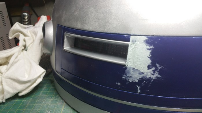
Now I used the filler. It was also around this time that I would have to paint, again.

Cured and sanded, still have some more work to do.
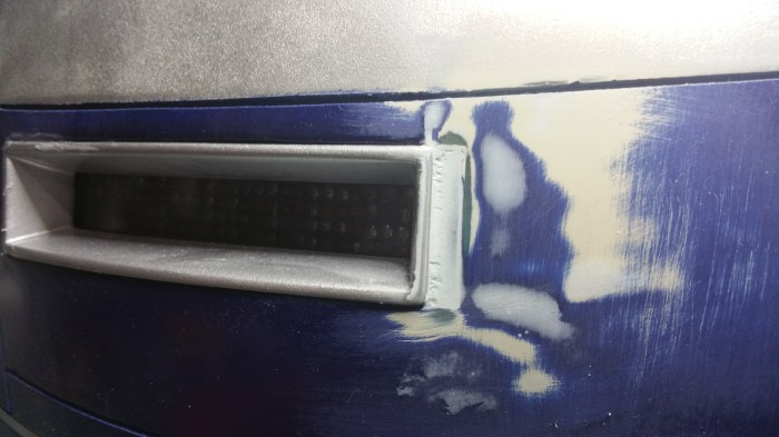
Used the different filler this time, it’s a bit “lighter”

Looking much better.

Here we go again.
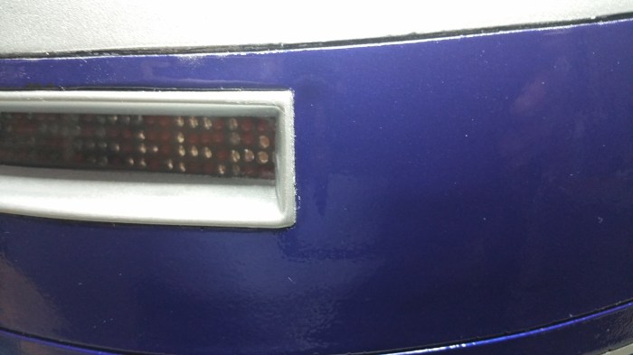
Fixed
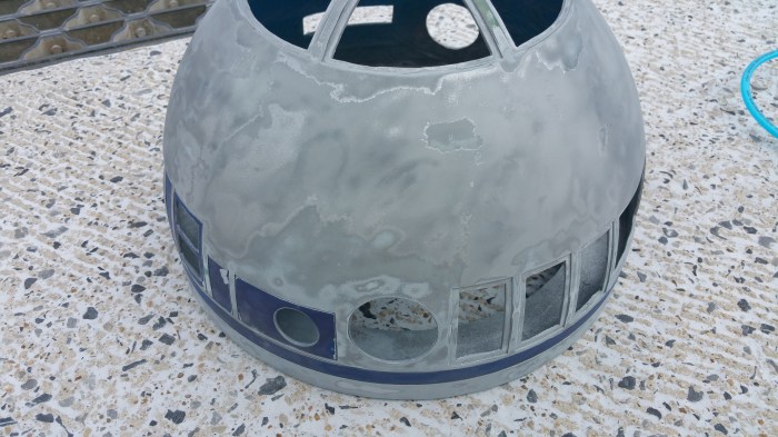
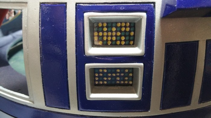
Lights on!
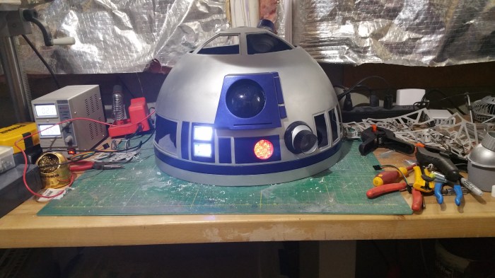
However, when I repainted the panel around the rear logics, a few painting mistakes may have been made. I ended up basically repainting the entire dome. I didn’t change any colors or anything so I didn’t take any pictures. It would basically be the same pictures you have already seen. However I did decide to put on a clear coat. More for protection then anything else. I had gotten used to the dull metal look, I was kind of hesitant to shine it up. I figured, if I ended up hating it I could always put on a matte clear coat.


Here are the results, I’m kind of liking how it turned out.
Next up, the panels. Closer, and closer.
