A long time ago…

Almost seven months to the day to be exact, since my last post. And for that I apologize. Real life got in the way, as it sometimes does. I had a grueling work schedule for about 6 month straight and just did not have time to work on R2. My schedule is now back to normal so I can get back to building.

This is going to be a pretty short post. I actually did this shortly after I finished with the skins. I think at the time I had decided to not to start 3d printing parts and just keep going with making styrene parts, because like I said I was “in the groove”  with that process. This part was me “finishing” off the body before going on to the the legs or skirt.


20160804_134121

Here is where I left off. The skins look great, except for one thing. It looks “flat” and like it’s made of plastic. Probably because it IS made of plastic. It’s not really the look I want to go for. Which can only mean one thing.

MORE PAINTING!

kerravonclapping


I could have just painted it white and have it look pretty good, but I read on the Astromech.com forums about some people put a coat of silver underneath the white. The reason for this is that during the lifetime of the droid it’s going to get bumped around a lot. From loading and unloading into vehicles to interaction with the general public to operator error, paint is going to get scratched and chipped. It will look more realistic and and to the natural weathering if there is “metal” underneath.

20160820_081059

What I started with.


20160820_081256

I really wanted to build up the paint a little bit to add more depth. So instead a just a few “heavier” coats I put on quite a few very light coats.

20160820_08162020160820_08252120160820_083614

This is coat six or seven. Really looking (I think) like the aluminum skins from the beginning of my last post.


20160823_165133

Now to turn it white again.

20160823_16592120160823_170748

Again building the paint up this after five or six coats. The doors and panels are really starting to “pop”.


20160827_083957

I had a couple of runs. (went a little too heavy on my last coat) but I figured the process of fixing it should demonstrate really well how  silver paint underneath will work.


20160827_084609

This is exactly the type of effect that I was looking for. It really does look like there is metal under the white paint. When I start to weather the paint job, this should really help to give a great look.


img_20170303_185028

Finished paint job.


Side by side comparison. I really like how it turned out.


So now that I can get back to work on R2 I decided that I would start 3D printing some of the parts that I need. I am going to try and get most, if not all, of the body done before I start moving onto the legs or skirt. I have actually started printing out parts a couple of days ago, so I hope to have another update really soon.


More than one way to skin a droid

The next logical step is to put a skin around the frame. Unlike the frame there are usually only two materials that are used to make the skin, aluminum or styrene.

20160618_141859

Aluminum skins.

To achieve the appearance of different panels and doors that make up the body of R2, four sets of skins are used. Two inner sets (front and back) and two outer sets (also front and back). In the case of styrene they are cut out of much thinner sheets (1mm) as compared to the frame(3mm). They also require a different technique to cut out. I was able to use the score and snap method only for the cuts along the edge of the skin. With all of the inner cuts I basically had to cut through the entire thickness of the sheet, which is a heck of a lot of easier with 1mm.

20160720_160805

Uncut inner back skin.


20160720_163207

First inner piece cut out. Most of the inner cuts are required to allow parts to be mounted through the skin.


20160720_165907

Inner back skin almost completed. At this point I still had not figured out how I was going to free-hand cut out the shoulder circles yet.


20160720_171417

Inner front. A little bit more complicated.


20160721_182248

The key to getting nice cuts is to always make sure you have a sharp blade. So sharp that I didn’t even notice that at some point I had nicked one of my fingers. Oh well. Now that R2 has had a taste of human blood, what the worse that can happen?

Christine


20160721_202706

Inner front, I still had not tried to cut any curves yet. Time to figure this out.


TO THE MATHS!

20160721_211512

First figure the radius.

20160722_135407

Find the center of a scrap 3mm piece.

20160722_140520

Cut out disk on the router table.

20160722_144048

I now had a cutting guide.


20160722_195321

Finished inner front. I was able to actually free-hand cut where the center vents are going to be placed.


20160725_171215

Outer back, Much more complicated than either inner skins.


20160725_175010

I had to cut wherever there is a black line. So I start from the center.


20160725_175519

Then the next set of lines.


20160725_180013

Then finally the outer lines. This method allowed me to give the straight edge as much support as possible so that I could make straight cuts.


20160725_182811

After I cut the parts out I labeled them and set them off to the side.


20160726_175634

Outer back completed.


20160726_182021

Outer front, intimidating.


20160728_163744

Hardly anything left over.


20160728_170952

A mockup of how it will look when both front skins are mounted on the frame.


20160731_182821

Making sure I am doing it right.


20160731_183839

Laying the inner front skin on the frame.

20160731_183909

Making sure it is center to the frame.

20160731_183712

Waiting for the weld-on to set up. Making sure the skin doesn’t move.

20160731_212418

Applying the weld-on to wherever the skin touches the frame.

20160731_212328

Making sure the top is lined up.


20160731_221010

First skin mounted to frame.


20160801_164006

The back was basically the same process.


20160801_164027

Side view.


Tina was at work when I mounted the outer skins to the inner skins, so not as many pictures. The weld-on sets up pretty quick so not enough time to take as many pictures as I had wanted.

20160802_174838

Woking from the center out to the sides.

20160802_184940

Front outer mounted to front inner. Starting to get some depth.

20160802_193849

The back.

20160803_203438

These are most of the detail parts that I had cut out earlier and set aside.

I really wanted to get the mounting of these parts right. These are supposed to be different panels and doors that could open up to reveal all kinds of different tools and gadgets that R2 would need. So I really did the best I could to make sure all the gaps were even and everything lined up.

20160803_212107

Started at the bottom of the front.

20160803_214539

Next tier.

20160803_222940

Third tier, also the first “doors”.

20160803_222955

Front almost done. There is one detail piece missing, it goes in the center. It’s blue so it will be easier to paint it first, before attaching it.


20160804_131034

The back worked pretty much the same way as the front. worked my way up from the bottom, “minding the gaps”.

20160804_131110

From the side you can get a look of the really long doors on both the front and the back.


20160804_134121

Just for fun, I wanted to see what it would look like with the dome. Not bad.


I have some options of where I can go from here. I can start building the legs, or, move on to the skirt, which sits right under the body, both of which I will continue to make out of styrene. Or I could continue with the body, but since most of the remaining parts are 3d printed I would have to change gears a bit in construction techniques. I’m on a pretty good roll right now with the styrene, but I also may want to switch it up a bit to avoid burnout. Not sure which way I want to go, yet.


It’s what’s inside that counts.

One of the biggest decisions I had to make when I first started, and one of the most asked question on the board is, What material should I use to make an R2? For the most part when people ask this they are usually referring to the body, and in extension the legs and feet. Although you can use different material for all four of the main sub-units (dome, body, legs, and feet), most people pick a single material and use it for their entire droid. Generally there are three main choices builders have. Aluminum, wood, and styrene.

Aluminum is the most expensive of choices. If you happen to hear someone say the spent 10-15k building a droid, it’s pretty much guaranteed that it is made completely of aluminum. It is also arguably the strongest/most durable material you can use. Also, I think the best looking droids are aluminum. But it will cost you. Not just the material, but the tools used to cut and shape it are more expensive as well. Plus the knowledge to use some of those tools may be a bit more specialized as well.
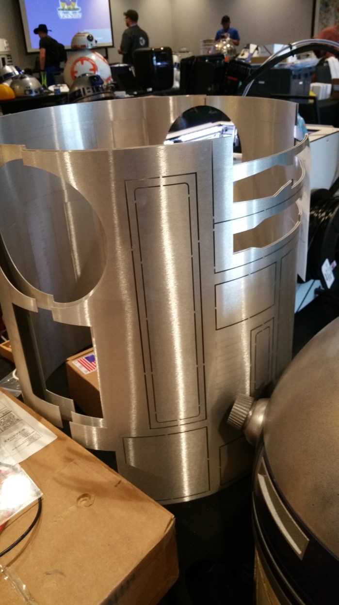
20160618_141947

Aluminum frame


Wood is probably the cheapest, depending on the type of wood. You can use pine plywood for the really inexpensive option, or go with Baltic Birch which is more expensive but much stronger and is a higher quality wood. Wood will probably be the heaviest. If you plan on having a stationary droid, weight is probably not a big concern. But if you plan on having your droid  mobile, weight could affect drivetrain decisions. Also could affect the size of the battery you may need. It would be very close to the strength/durability of aluminum. Some might say it is better than aluminum in this regard.  You would just need normal woodworking tools to construct, but that might include a table saw and router, which may necessitate a larger shop/work area.

20160618_141808

A Baltic Birch wooden frame


The third option would be styrene. High Impact Polystyrene to be exact. This is not the same as the polystyrene used by some fast food places for food containers. As the name implies, it is much more dense. You can buy it in sheets like plywood. It’s not nearly expensive as the aluminum option but not as cheap as some of the wood options. It’s the lightest of the three, but that also means that it is more fragile than the other two, and may be more susceptible to the frame twisting a little when it is being driven around.  All four main sub-units can be built with just using hand tools. A sharp knife,and a straight edge is really all you need for 90-95% of the build. You can use power tools, but they are not necessary.
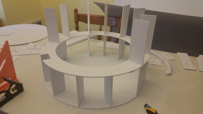
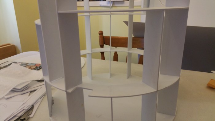
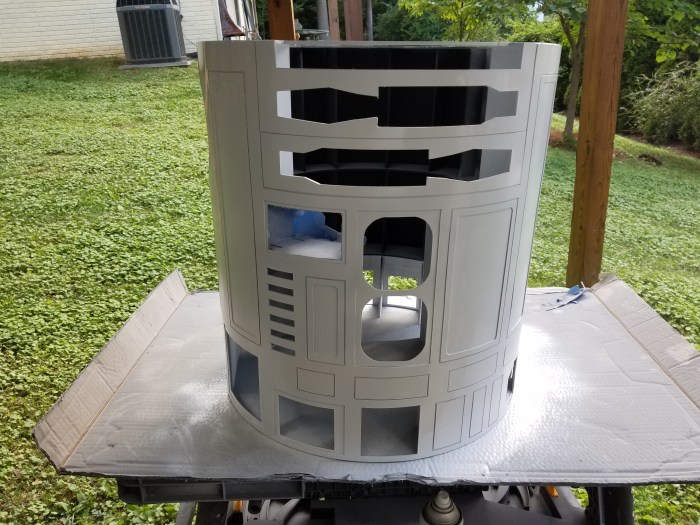
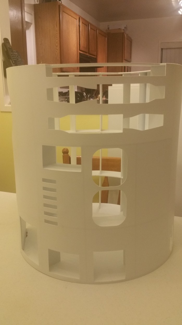
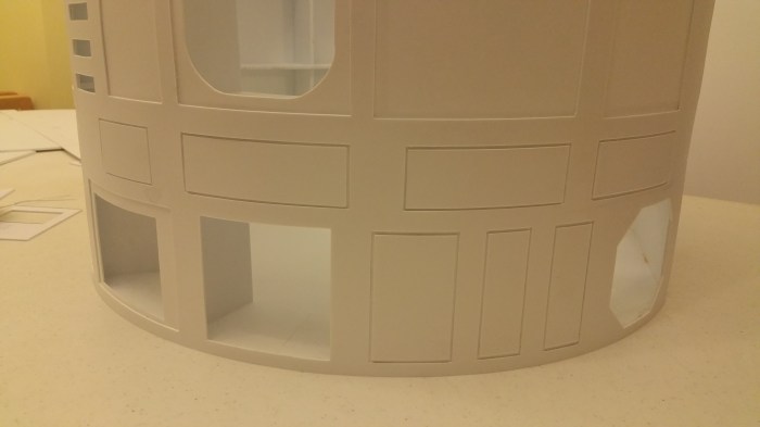
 

styreneframeexample

Styrene frame


I chose styrene. I am limited on my work space, and I am not prepared to shell out anywhere near the cost of an aluminum droid. Also, with aluminum , most of the time you basically buy an unassembled frame with all necessary parts/pieces pre-cut, and put it together like a kit. (With aluminum that really is the way to go, unless you have access to a full metal/machine shop I think it would be extremely difficult to make one on your own.) There are also wood and styrene pre-cut kits. There are some really nice options for all three, and I was VERY tempted to get a styrene kit.

I was really nervous before starting in on the frame. I had never really done anything like this before and was afraid that somehow I would really screw it up. The frame is pretty critical to get right.  That is one of the reasons I waited until after DroidCon to start building again. I was hoping to get some ideas from builders who had, or were in the middle of using styrene for their own build. Unfortunately I didn’t see any, pretty much everyone had an aluminum or wood frames.

After being unsuccessful in this particular quest at droidCon, when I got back home I started really scouring the message boards on the builder web site for any tip and tricks.  Which I found a few. But I kept looking at the pre-cut kits people were selling and thinking how easy it would be. These parts would be laser cut so they would absolutely be the correct size, all the edges would be smooth, everything marked exactly how they are supposed to be, etc. All my worries about this particular step would disappear.

I didn’t buy one. For two main reasons. First, I had already bought the styrene sheets. While not necessarily a waste, I could always use them to build a second droid sometime in the future. I would just be delaying the process. Second, I really like the idea of building an R2 not “just” assembling one. For some people buying this type of kit is absolutely the best way to go for their particular situation, and I would not think less of anyone who does/did. Or think that somehow my droid is “better” because I didn’t. Heck, my dome could be considered to be in this vein. Although nothing was pre-cut everything was already molded in the dome itself. Also most likely if I do indeed build a second droid I probably will buy pre-cut pieces.  It may sound a little bit corny, or cliche but I decided to build it BECAUSE I was so nervous about it. I did it BECAUSE I thought it would be hard (to paraphrase JFK).

Now in retrospect, now that I’ve completed the frame, I had nothing to worry about. In fact I actually really enjoyed putting it all together.


Here’s how I did it.

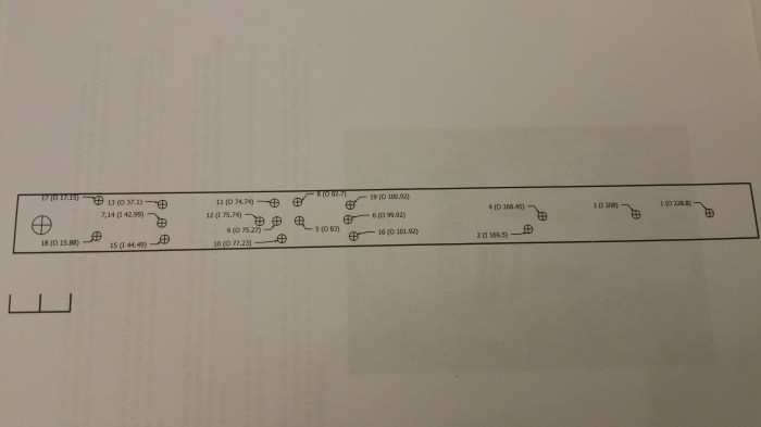
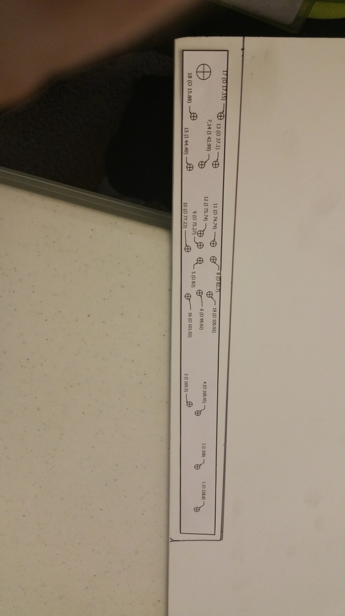
First thing I did, after deciding on styrene, was to look for plans. Unlike my dome which didn’t need plans, I will need a set of plans to help me build most of the rest of the droid. There were several to choose from, but the ones I choose are made by the founder of the club Dave Everett. But that is not necessarily why I chose them. I mostly chose them because I could get them already printed out to the size needed and they come with an instruction manual.

20160729_121948

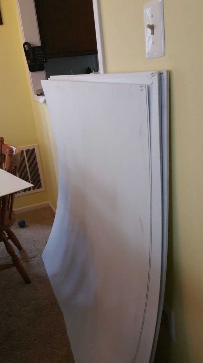
They came in a tube that is over four feet long.


20160729_102432

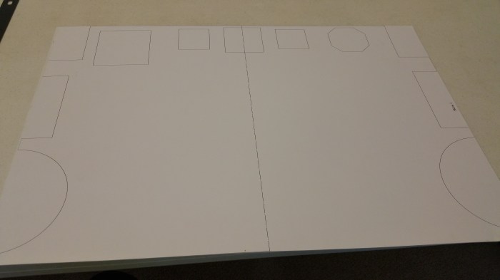
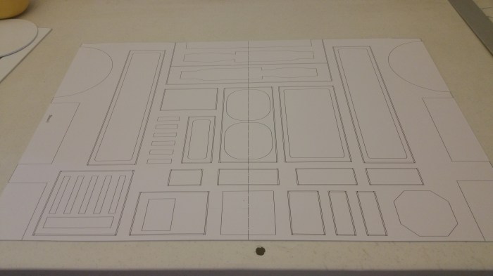
It’s not really a set of blueprints, and I have been careful not to call them that. They are more in the vein of clothing patterns. They are actual size. I glue them onto the sheets of styrene and just cut along the lines.


20160707_123433

20160729_125234.jpg

The instruction book. I probably might have figured how everything goes together, but this book made everything so much easier.
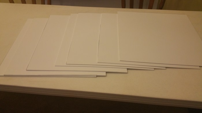


20160709_153514

The styrene

20160709_153430

All sheets are 4′ x 4′ I started out with 4 3mm, 1 1.5mm, 2 1mm sheets.  One of the “issues” that I have to contend with, in using Dave Everetts’ plans, is that everything is in metric. Thankfully, I’ve got used to dealing with metric using my 3D printer. However that doesn’t help when the plans call for a screw that is 4mm x 50mm, and the local hardware store doesn’t stock metric. Thank god for the internet and free shipping.


20151010_161827

This is my “work shop”. The table is only 6′ x 2′ with only a usable workspace of about 3′ x 2′. No way I could do what I need to do here.


I love my wife. And not just because she let me take over the dining room.

20160705_180552

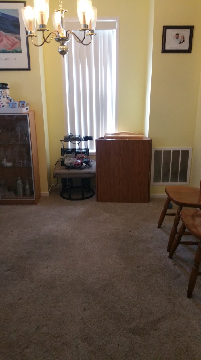
I had to clear out some space for a work table.

20160705_180736

Much better.


While I could of done all of the cuts with hand tools, I decided to cut all of the circles, and there are quite a few of those, with a router. The first thing I had to do was build a router table.

20160711_171847

I laid out where the router bit will stick through and the four places that the screws will go that will actually attach the router to the table.

20160711_173303

I used a trim router. Which is basically a smaller,lighter router that you are able to operate one handed. However, I chose one because it is mountable directly to a surface.

20160711_173321

The working side of the table. The screws that attached the router to the table are countersunk so that they do not interfere with the material being cut.


20160707_123446

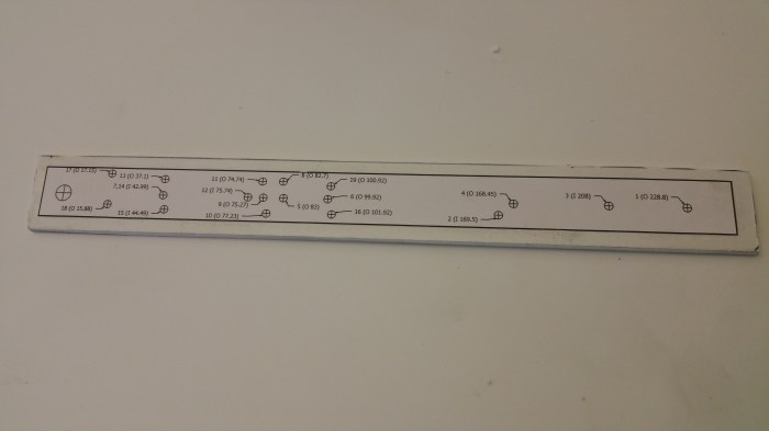
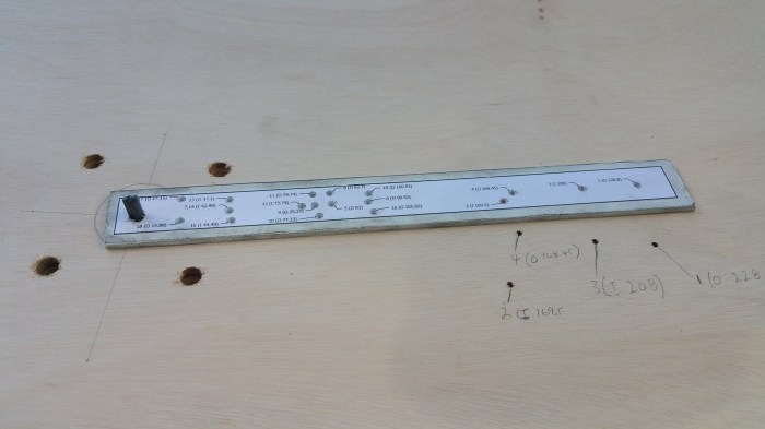
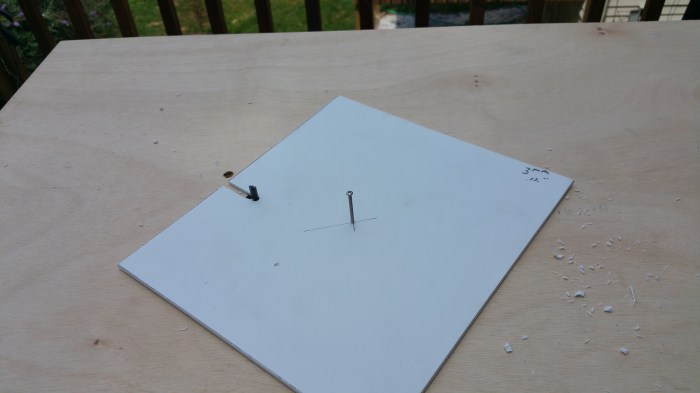
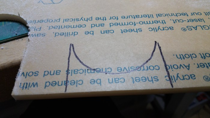
In order to get the correct size circle cuts I needed a radius guide, fortunately the instruction book had one that already has most of the correct radii that I needed. But a paper guide will not have done me much good. The first thing I had to make out of styrene was a guide that is a bit more durable.

20160707_131117

I cut out the paper guide and glued it down to a corner of 3mm styrene.


20160729_102604

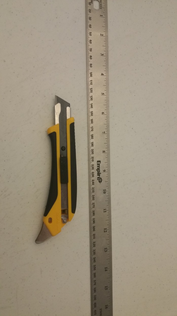
Here are the only tools I used for 90-95% of building the frame. The front portion of the blade can be snapped off. I did this a lot to ensure I always had a very sharp tip and  cutting edge.


20160707_132801

The length and the width really is not important so I cut it out a bit bigger just to make it easier to drill the holes in the proper locations.


20160707_133536

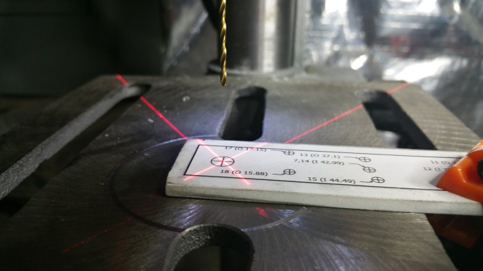
The holes need to be pretty precise, this one most of all. This is the hole that the router bit will go through.   All of the measurements are based off of the location of this hole. So I used my drill press to make a pilot hole as close to the center as I can get.

20160707_133949

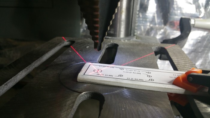
I then used a stepper bit (sometime times called a Uni-bit) to get it to the correct size. The pilot hole that I drilled before will help guide the bit to the proper location and also gives me a little bit bigger target to hit with the drill.

20160707_135634

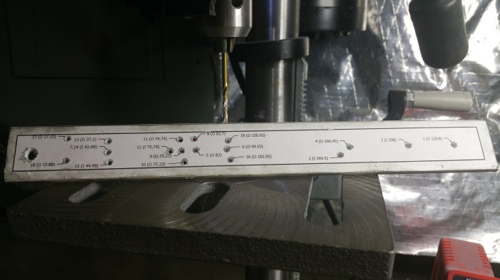
I drilled out the rest of the holes. These holes will place the center of the circle that I want to cut out the exact distance away from the router bit.


20160711_175604

I then transferred all of these to the router table. I then drilled through the table at each spot.


20160711_180840

Most  of the points are transferred and all of the ones that I will need for now.


Now on to actual parts.

20160709_200837

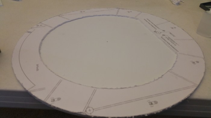
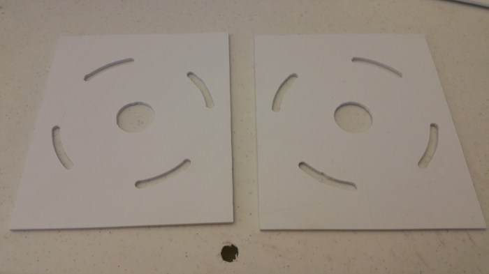
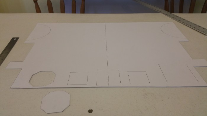
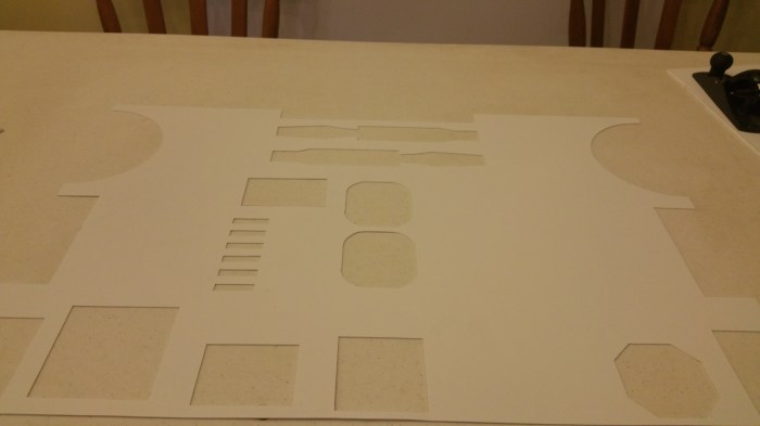
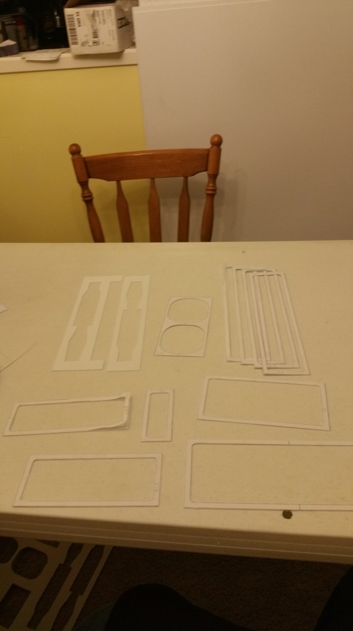
First off, I cut out the patterns from the plans. I don’t need to be exact, just enough to get the rough shape.


20160709_201154

I then cut up pieces of styrene.

20160709_211240

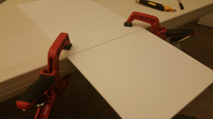
The easiest way to cut out the pieces is by using a “score & snap” method. I score a line along the plastic where I want the cut to be. It doesn’t need to be very deep at all, just three or four passes with the blade is usually enough.

20160709_211304

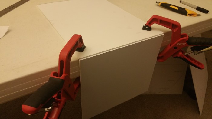
Then just bend it a little bit and it will snap right along the line that was scored. 3mm is pretty thick so I used clamps to start out with, but I pretty quickly discovered that they were not necessary,  it wasn’t too hard to snap just using my hands.


20160709_202759

Next I glued the patterns on to the pieces of styrene.

20160729_102512

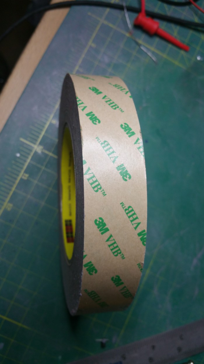
This is the glue I used. I have come to find out that this might have been a little bit of over kill. 3M make a less stronger spray glue, for temporary purposes. This stuff makes it very difficult to get the paper off of the plastic once I no longer need it. I basically have to soak it in a citrus based cleaner for a couple of minutes, but once I do that it comes right off.


20160709_213021

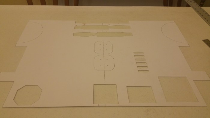
The rest of the parts I will need for the frame all glued to styrene.


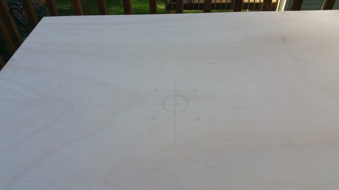
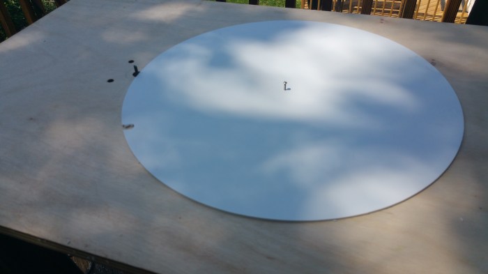
Time to cut some circles.

20160711_181337

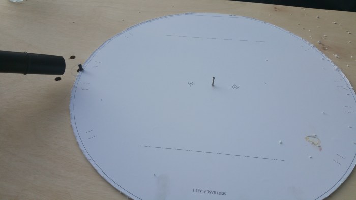
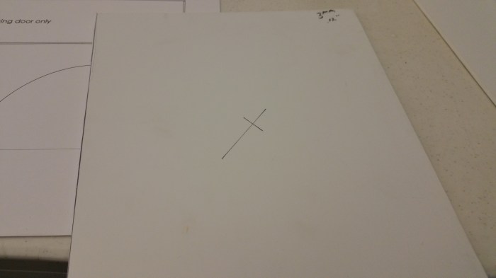
It’s kind of hard to tell from this picture, but I had to drill a hole in the center of each part that I will be cutting with the router. This will be the pivot point. The hole is the same size as the holes I drilled earlier through the table.

20160712_193159

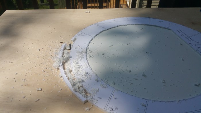
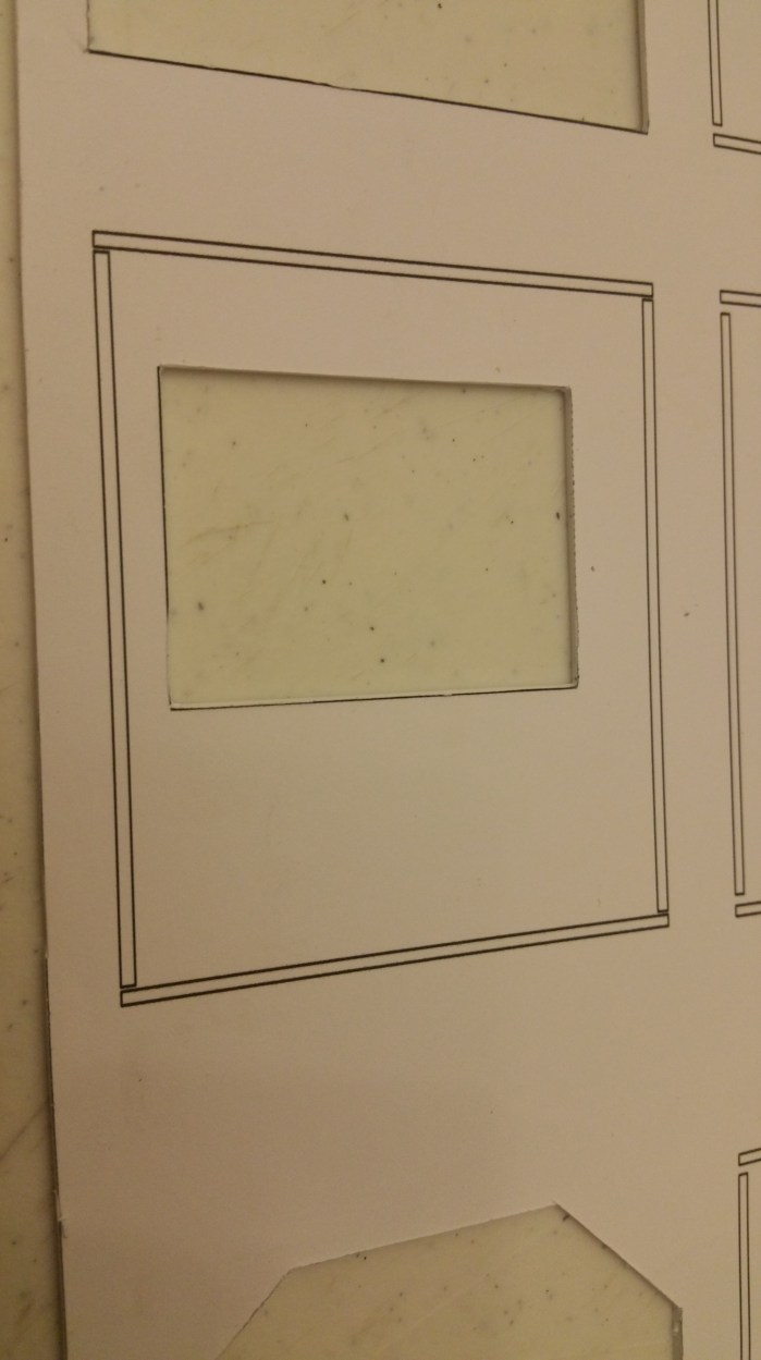
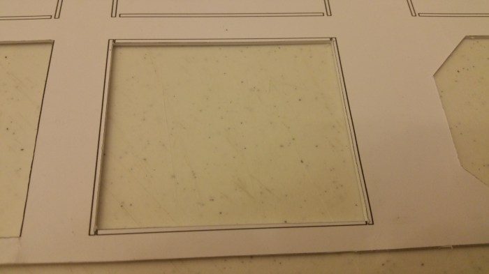
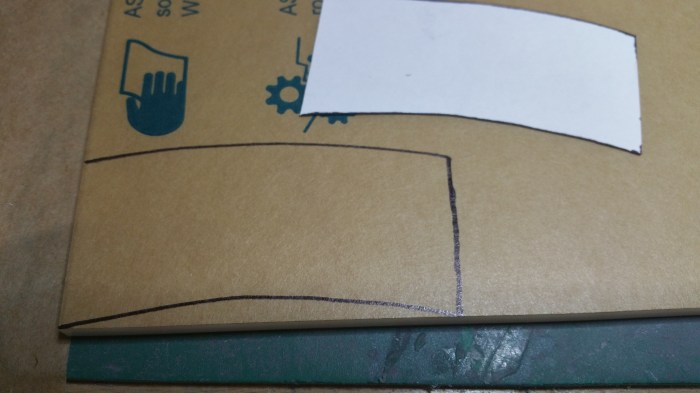
I then cut free-handed with the router to get to the very edge. doing this allows me to place the part in the correct position.  This is also a good shot of the guide lines. the dashed lines represent were a part will have to be placed later on in the building process. after cutting the piece out I ran the blade down the lines a couple of times so that they will still be there after I take off the paper.

20160712_193251

You can see the screw that I am using as a pivot. it is the same size as the holes both in the center of the part and that goes through the table. this way there should be very little to no wobbling of the part as I rotate it.

20160712_192811

At first, I did a rough pass that would get the size of the part very close to the finished size. Then a second pass to get it down to the correct size. I had read on the boards that I would achieve a smoother cut if the router bit didn’t have to cut on both the inside and the outside of the bit at the same time. After the first few parts I noticed that it was pretty smooth regardless of how many passes I did. I quit doing two passes after that.

Making a final pass. Tina was the camera operator.

20160712_195634

Some pieces are just rings and not a complete disc. So I had  to make a couple of passes. I had to make sure I cut out the outer portions first. Otherwise I lose my pivot point. This will be important later.

20160712_165940

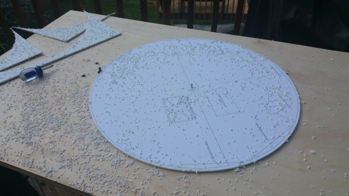
Cutting with a router creates a lot of “dust”.  A LOT. Thank god for shop-vacs.


20160710_142024

For the non circular pieces, it is pretty easy. Just score and snap. I used a clamp on some of the smaller pieces to make sure the straight edge stayed on the line I needed to cut. Yes, that is a wood plane. It was very useful in making the edges square to the front of the pieces.


20160713_193818

All the pieces of the frame cut out and ready for assembly. Total time, about 15-20 hours spread out over a week or so.


20160714_164750

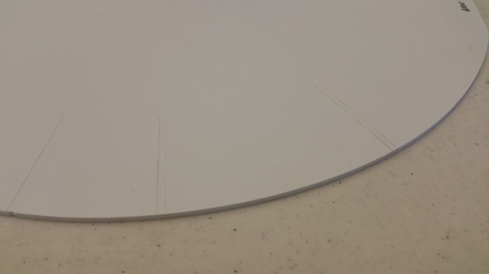
This is what the guide lines look like after I take off the paper. I placed the uprights on these marks.

20160729_174626

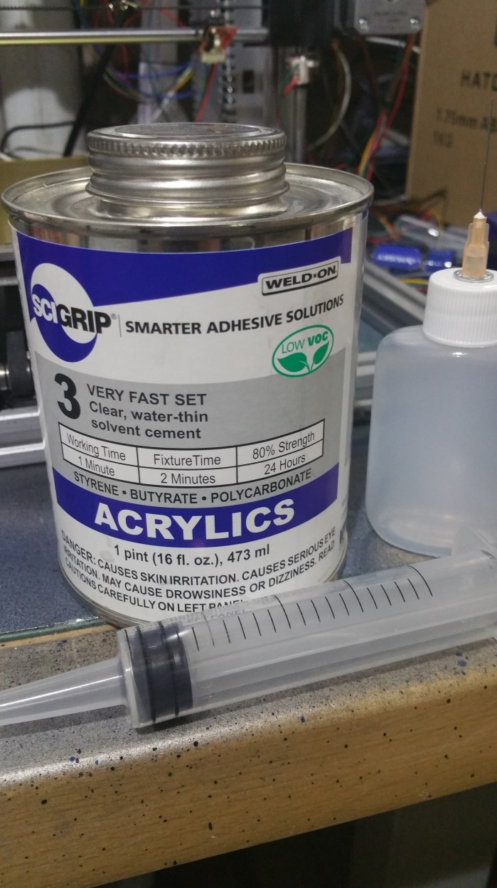
This is what I used to glue everything together. It’s called Weld-on 3. It’s not really glue though. It works a lot like welding two pieces of metal together. It will chemically melt the plastic it’s designed for (in this case styrene,butyrate, and polycarbonate acrylics)so that if you apply it where two pieces come together it will melt them together, making it essentially one piece. It’s as thin as water, and just as clear, and it evaporates very quickly. That’s why I need to use the needle applicator. I used the syringe to transfer it from the can to the applicator.

20160714_164504

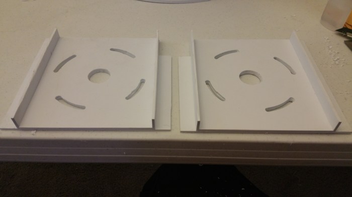
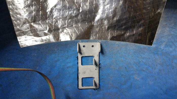
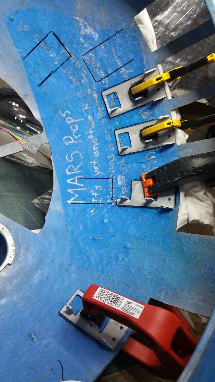
The first parts I needed to “glue” up. These are anke inset plates. they will go on the lowest “layer” of the frame.

20160714_165111

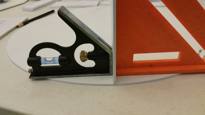
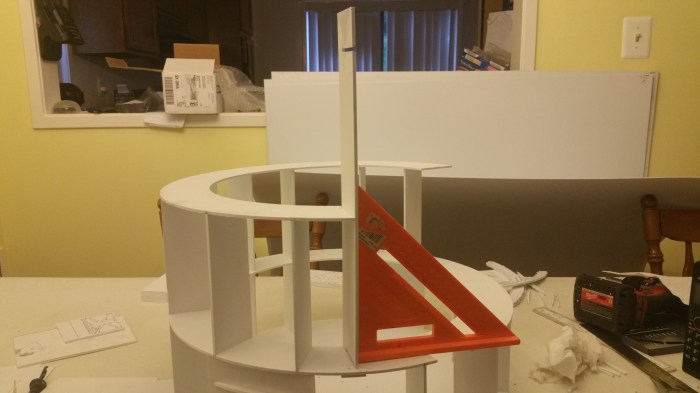
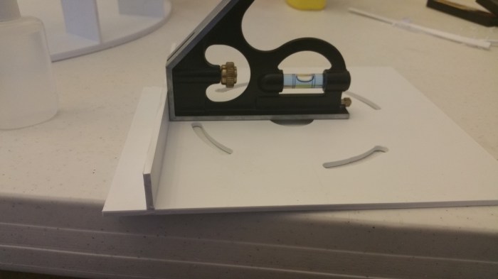
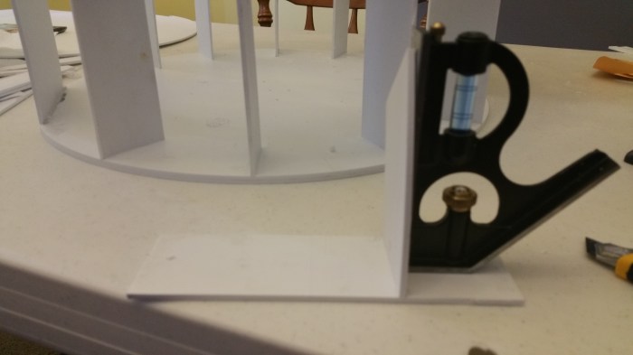
The first piece of the actual frame. I need to make sure that they are square.

20160714_165153

I also need to make sure that the pieces are flush to the disc beneath it. Also if you look really close you can see the where I put the Weld-on 3 in the corners.


20160714_170825

The fixture time on Weld-on 3 is 2 minutes. After about 5 minutes I felt comfortable enough to take off the squares to let the piece stand on its own.


20160714_171113

Didn’t have enough room for two squares for the rest of the pieces.


20160714_172949

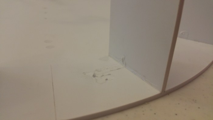
I was still getting used to using the Weld-on. I used a little bit too much, and it got under the metal square.

20160714_192751

Had to get a little bit creative on the ankle insert plates.

20160714_193942

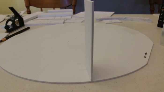
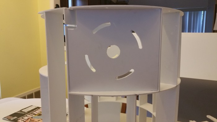
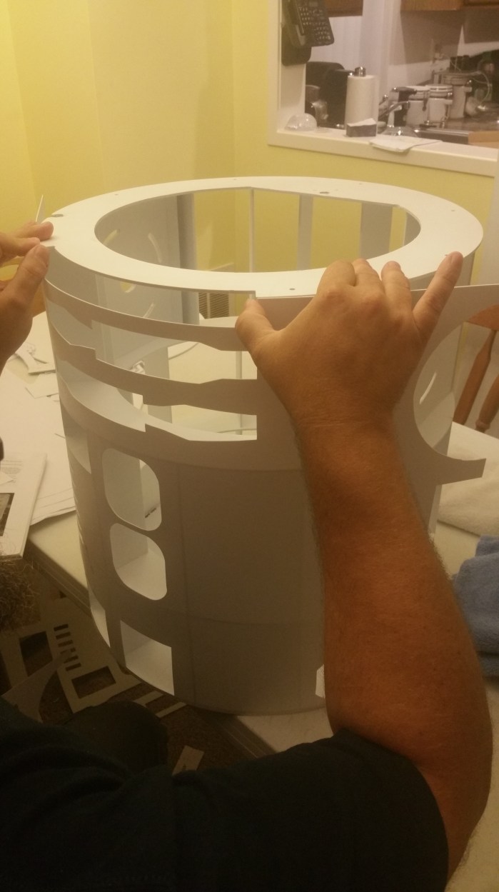
First set of uprights complete. I let this set up 24 hours before I went on to the next step to make sure they would be able to support some weight.


20160716_065847

I didn’t get a picture this time, but in order to get this piece glued on I flipped the first layer upside down on top of the underside of this top ring. I then replicated the process I used earlier to make sure the pieces were square to this ring as well.

20160716_065928

From another angle

20160716_074734

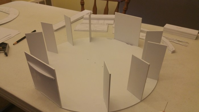
Starting the second layer. Trying to be a bit more efficient using two squares on different pieces as much as I could.

20160716_092115

Middle almost done.

20160716_154338

This is the process of flipping the assembly over on top of the next plate to make sure the parts are both in the correct place and square. Since there are no guide lines on the the bottom of the plate I transferred the the marks to the edge. You can see them right under the part that is being glued down. The one to the left of that still needs to be moved into the correct place before being affixed.


20160716_185435

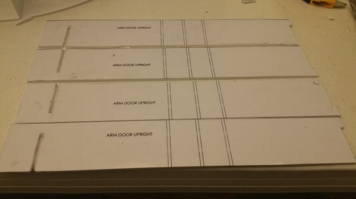
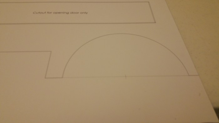
The next parts are the arm door uprights. At this point I still had not decided on whether or not to make these door openable or not on my R2. So just in case, I cut the slots both at the bottom and near the top. These will allow hinges to be placed and pass through the frame.

20160716_190354

Placing the arm door uprights. This proved to be a little bit interesting. Both because this is the first time I had to glue a piece in the middle of another one. But also because I decided to cut out the hinge slot I had very little support on the bottom.

20160716_211718

The rest of the middle layer. I also realised that I only needed to cut hinge slots in two of the arm door uprights. But since I am building out of styrene it was not too much of a big deal to grab some scrap pieces and remake the pieces.

As I went to attach top plate I realized that I had made a  mistake. When I was cutting it out I did not notice that there was a piece around the outer edge that needed to be cut out. it was about a foot long  about an 3/4 of an inch deep into the edge and follows the curvature of the ring itself. Unfortunately I did not get a picture of it. The problem being I had already cut out the center so I had no pivot point so I couldn’t  cut it out with the router and I did not want to try and cut it out by hand. I couldn’t put the pattern on another piece of styrene be cause it was still on the existing piece and  the patterns are pretty much destroyed taking them off. After a day or so the solution hit me and I was kind of upset that I had not thought of it earlier than I did. If all I needed was a pivot point, all I needed to do was make another one.

20160716_145159

I cut out a blank disk, the same size as the ring.

20160716_150508

The piece I need to cut out is on the left hand side of the ring. I  very carefully lined up the two making sure they were flush all the way around. I then put just a few spots of weld-on around the inner edge to make sure they would not come apart while cutting, but still easy enough to cut apart afterward.

20160716_151444

The router bit sticks up far enough to cut through both pieces at once. Problem solved! Also did I mention that using the router without a shop-vac is VERY messy.


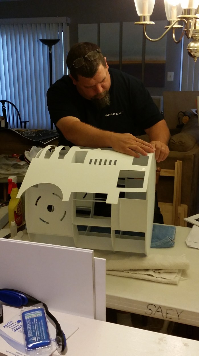
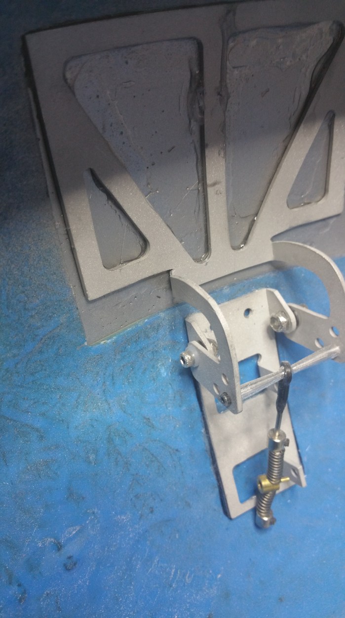
The next part I needed to make was the shoulder plates. A lot of the weight of the complete droid will be supported by these plates so they have to be pretty beefy.

20160717_160602

There will be two of these support flanges on each piece.

20160719_162730

I made up two support plates so that I can double up the thickness.The slots are cut there so that I can rotate R2 into a upright position, instead of his normal lean-back position.
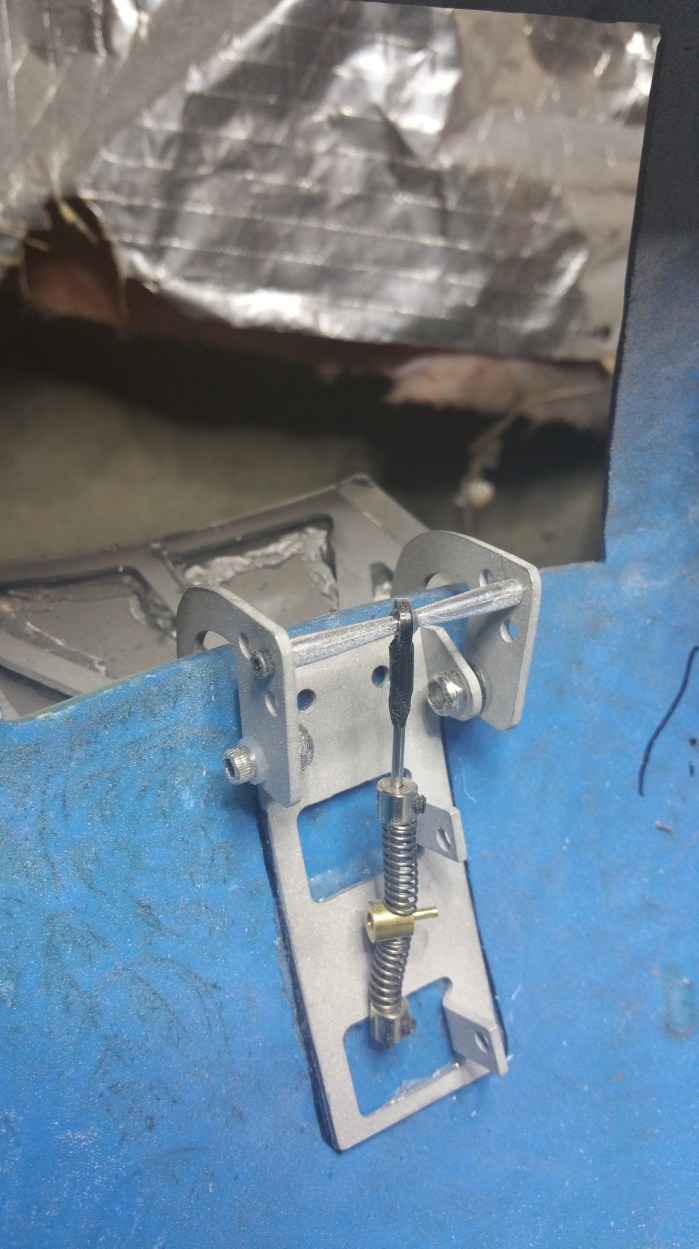
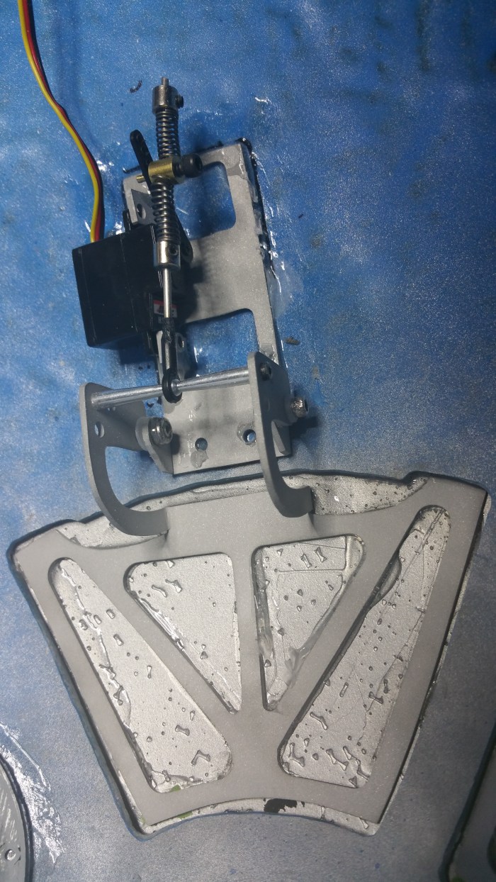
20160719_170733

Finished pieces.


20160719_175637

They go in at the top of the frame.


By this time I had decided that I was only going to have one door that opens in the body. That was going to be the charger bay.

ESB-Power-Jack

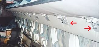
As seen here in Empire. I will use it exactly like it was in the move. It is were I will plug in my batteries for recharge.

framechargerbaylocation

It’s has to go right about here.

When I went to put in a piece that would be the bottom of the bay, I realized that I had screwed up a little bit again. The two center uprights were upside down. I knew that they were upside down because the guide lines, for the charge bay bottom piece, were closer to the bottom than to the top. I hadn’t noticed the lines when I glued it on to the plate. Fortunately, it was not that hard to remove piece. I just did a version of the score and snap method.

20160719_180951

Taking out the support also solved another problem that I was having.

I couldn’t figure out how I was going to attach a stand alone horizontal piece between two uprights, unsupported.

20160719_181026

With the upright taken out, I wouldn’t have to. Even if I hadn’t put it in upside down this is probably the solution I would have come up with anyway.

20160719_185206

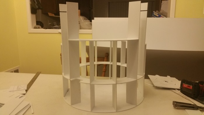
Charge bay constructed.
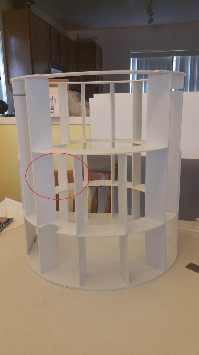
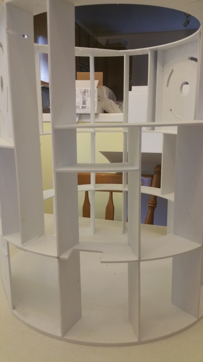
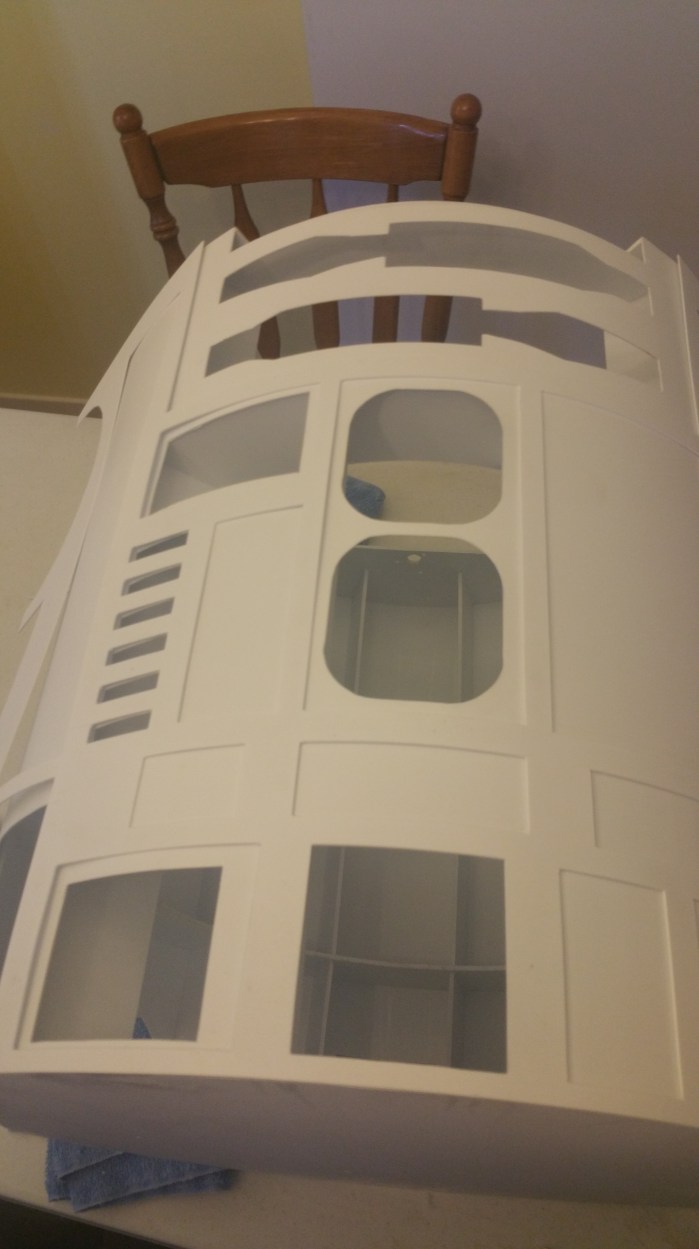
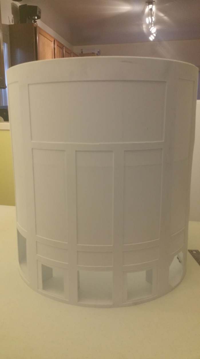
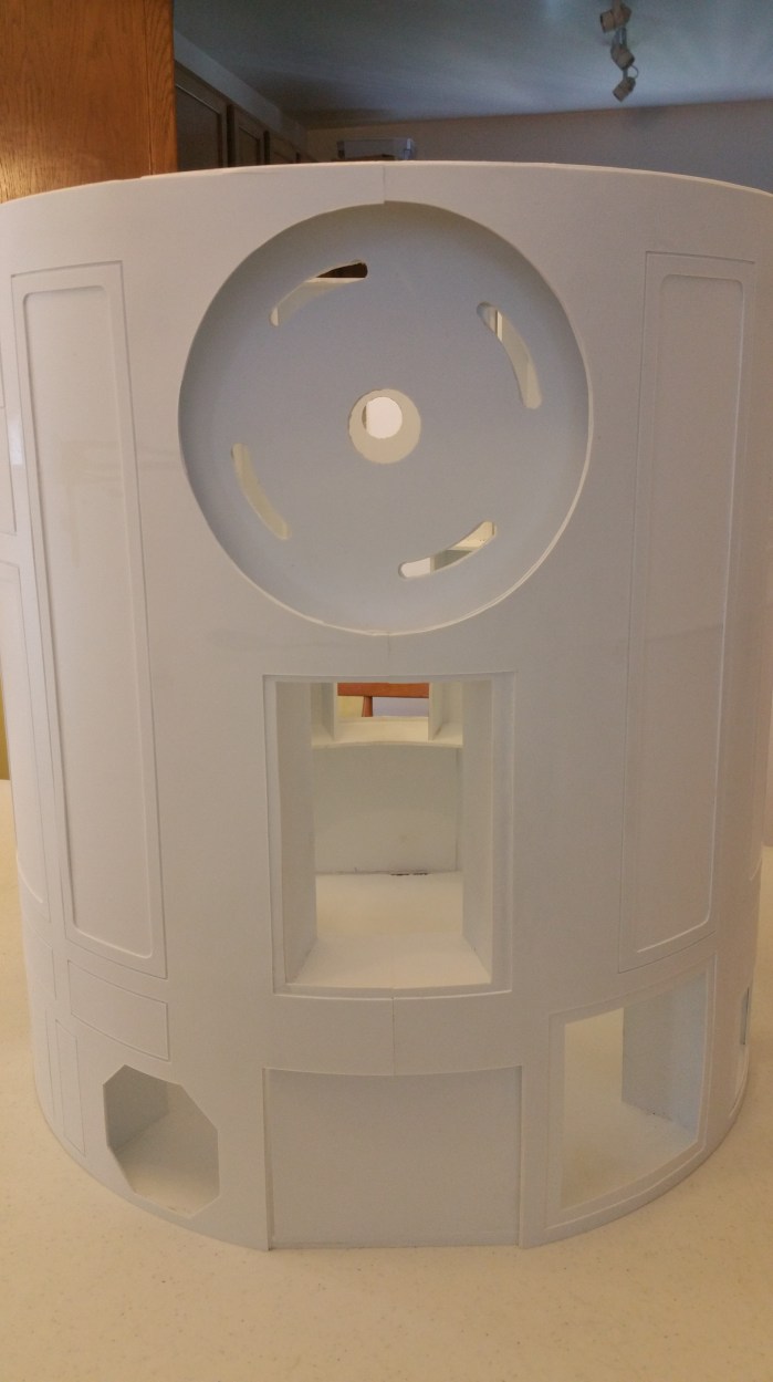
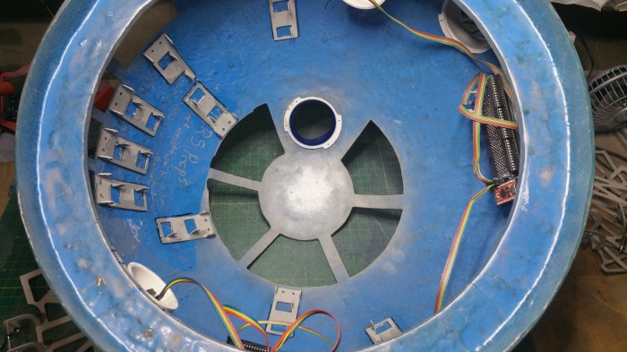
 

20160730_093000

Completed frame.

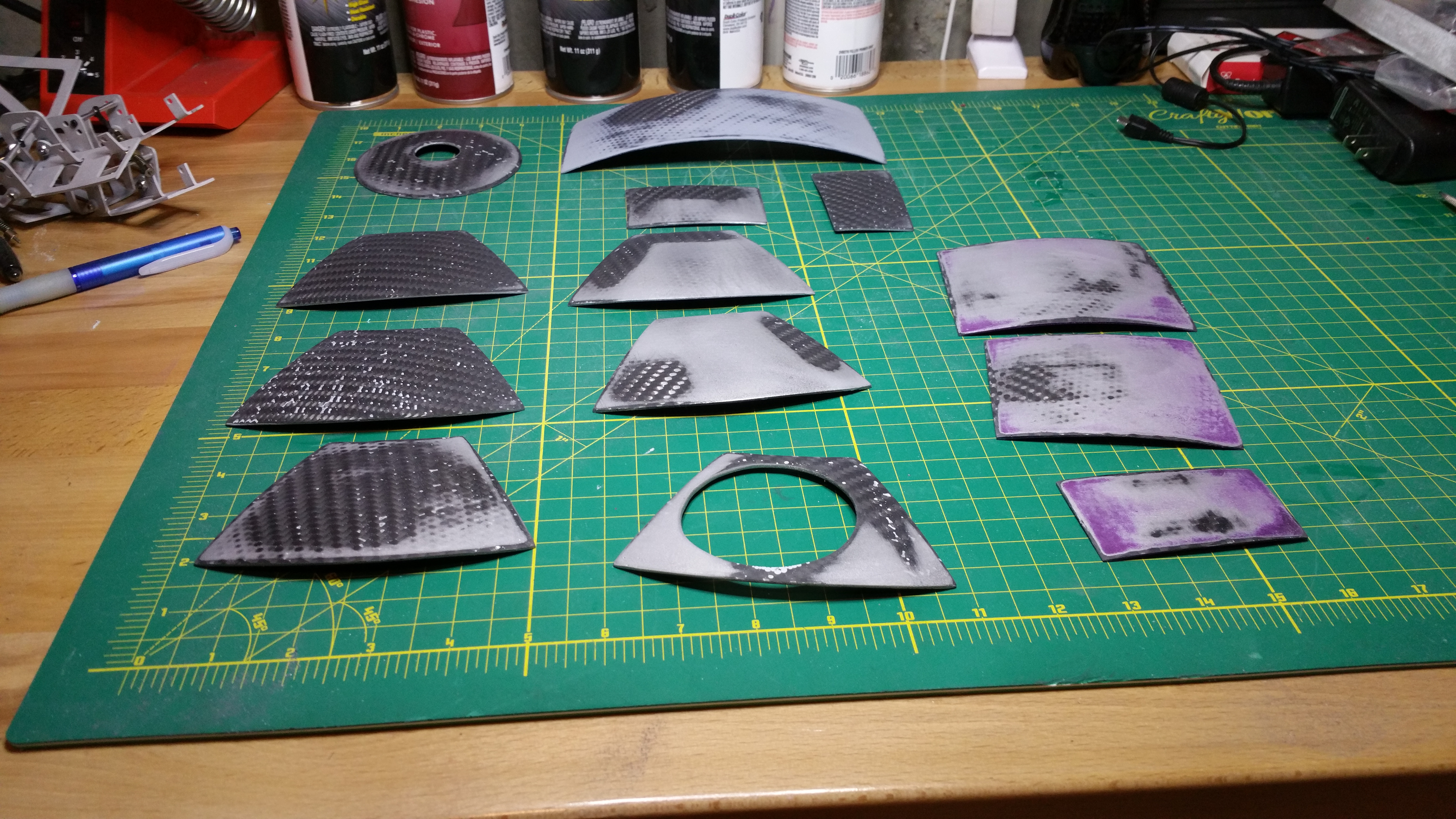
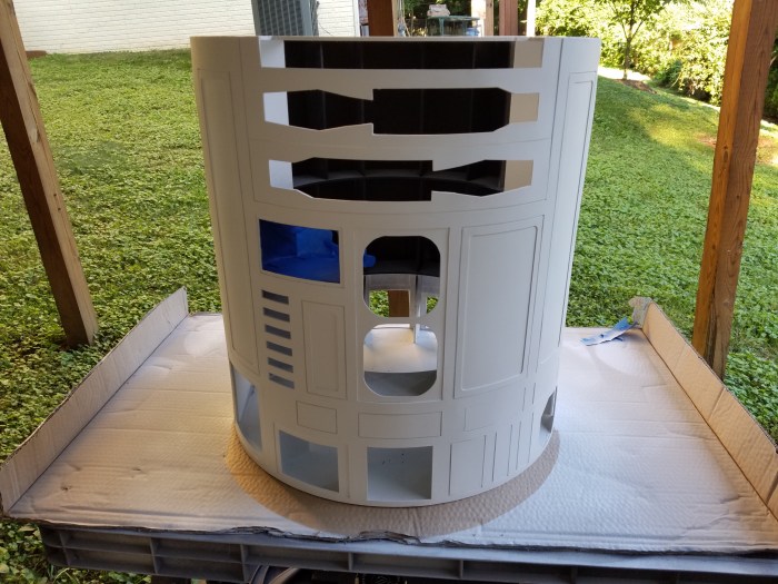
Next step is to put on the skins. The skins wrap around the frame, and are made out of 1mm styrene.


DroidCon4

Sorry it’s been a while since I last posted anything. But like I said on my last post, I wanted to at least attend DroidCon before I even started on anything new with R2. Also to be honest I was a little bit burned out on all thing R2. But strangely enough immersing myself in all things droid for a full weekend at Droidcon really got me wanting to start up again.


20160618_151714

Droidcon is a four day (Thus.-Sun.)get together for the R2 builders club. So far it has been held every two years in Indianapolis. The one I attended was the fourth one. Unfortunately I wasn’t able to get enough time off work so I was only able to be there on Sat. and Sun.

20160618_171828

It was held in  a couple of conference rooms at Holiday Inn. From what I hear, about 100-150 people attended over the entire weekend. Also in attendance was about 30 droids.

20160618_100347

Your “standard” R2 lots of these guys of course


20160618_134727

This is an R5 droid, R5-D5 to be exact, you can see his “bad motivator” on the top of his head.


20160618_094134

Not so “standard” R2


20160618_094428

BatDroid? Although a belt, especially a utility belt, raises some interesting questions


20160618_09430720160618_094111

Various R2’s in many colors and stages of completion.


20160618_095846

A BB-8 under construction. There were two or three of these guys there.

Including one that moved about, although I didn’t get a chance to get a video of him rolling around.

And an 8 bit/Minecraft version. The kid riding him, built it.


20160618_094357

A battle droid even showed up.


20160618_100452

I really loved this blueprint


20160618_164433

Group Shot.


20160618_165259

Some of the lady members of the group


20160618_164839

And just the droids themselves, plus one very excited Jawa.


20160618_184916

Little bit of history of the club.

I had a really good time. I got a lot of good tips and some ideas about my R2. I can’t wait to go back in two years. However the next big gathering will actually be at Celebration VIII in Orlando next year. It is still undecided if I will make to that one or not.

I have actually started working again. and have completed the basic frame and have started to work on the outer “wrap” that goes around the frame called the skin. Hopefully I will have that post up VERY soon.


Almost There

It’s finally time to install the movable panels. This actually took quite a while to do, because at this point everything starts to tie together. So the first thing I needed was to build the domes’ “brain”.

I decided to go with a system designed by a guy on the Astromech forums by the name of CuriousMarc. It called a MarcDuino. It is powered by a Arduino similar to the mini computer used to control lights. It’s a pretty powerful board, that combined with an Iphone app, that he also designed, can control pretty much everything under the dome.

20160327_124120

This is the “blank” board. As you can see this is version 1.1. There is a version 2.0 but it’s not DIY friendly. And although there are some upgrades to the 2.0 board, there is nothing that I absolutely needed.


20160206_112454

First thing I do is solder on all the connectors.


20160206_113648

Next is the capacitors.


20160206_114129

Resistors


20160206_114741

L.E.D.’s


20160206_120110

And Finally the Arduino itself. I usually solder my boards in this order as much as possible. With the most heat”sensitive” components last.


Now onto the dome.

I decide to use hinges that the maker, another forum member  KevinHolme, calls the Ultimate Hinge. 20160109_183818

They are very nice hinges. They will allow the panels to open up to 90 degrees. They also have a lot of surface area in order to allow me to glue the panels to the hinge.


20160121_171051

In order to make the hinges fit in the hole I needed to enlarge them just a bit


20160219_170831

After that I marked out where each one will end up going. This kinda made me a bit sad because I realized that I would be covering up the quote from the guys that made the dome.


20160220_182325

First one done. I found it easier to both mark and glue them if I took the hinges apart.


20160221_140450

Because the glue I use takes 24 hours to fully cure, this took a little while. I think almost a full week. I “only” have 11 panels, but because of the shape of the dome and the size and shape of some of the holes I could not use all of my clamps at once.


20160223_162956

Two more to go, I started to realize how crowded it was going to get in here.


After all the the hinges were glued I attached the second parts. The nice thing about these hinges is, since they are made of aluminum,  I will be able to tweek them a little bit in order for them to open and close correctly.


20160308_162601

In order to attach the panels to the hinge itself I need glue them to the hinge. I obviously didn’t want to glue the panels to the dome itself so I put some masking tape around the openings.


20160224_173704

Put on a copious amount of glue.


20160305_143316

Align panels, and clamp. Again, because of such a long dry time and physical limitations it took another week to complete putting on the panels.


Panels on and power applied to the lights. This is the same video put on my facebook page.


Second video I did not post, showing off the back of the dome.


At this point I could have stopped and called it a pretty successful build. But obviously I did something with those hinges that took so long to install. Next step install some servos.

What is a servo?

20160320_120544

This is a servo. Servo is short for servomotor. It’s kinda like a DC motor that can be precisely controlled.  Instead of just spinning around and around like a regular motor, you can control exactly where the motor will stop.


Like this. This servo is connected to the MarcDuino I just built. I can control precisely where the motor stops and which direction it spins.

The other board red circuit board that is also hooked up to the MarcDuino is called a WiFly.


20160320_121710

It is a WIFI radio.

20160320_122236

I hook it up to the MarcDuino so that I can control it through the App R2 Touch


20160320_122745

Running on an Ipod. Through this app I will be able to control pretty much anything that happens under the dome.


The first thing I need to do with the servos is install a new arm.

20160320_123335

The new arm is much longer which will allow a much longer arc of movement. which will be needed to fully open and close the panels.


20160320_125154

This is the hinge closed. The brass part is the pin that will be inserted into the servo arm. notice that it is right near the lower servo mount point.


20160320_125222

This is the same hinge opened. Notice the pin has raised just about 2/3 of the way to the top servo mounting point. That’s about 3/4 of an inch. The small arm just does not have the length to travel that far.


20160320_125238

Here the servo is mounted into the hinge.


20160320_125441

The hinge arm is connected to the servo arm in the closed position.


20160327_145018

This is the same hinge now in the open position.Notice that the pin on this one, when the hinge is open, is right at the servo mounting point. You’ll also noticed that I removed the springs from the hinge arm. I did this because it allows greater flexibility on where exactly I can  put the pin on the servo arm. When the springs were on i was limited, and because of that when the panels opened, the hinge would be completely open before the servo finished moving. The servo kept trying to get the arm into the correct position, but since it couldn’t it would sit and there making a jittering noise that was pretty loud. Especially when 7 or 8 of the servos were doing it.


20160327_145332

All the servos hooked up to the MarcDuino. This is not the final mounting point for it. I’m not sure exactly yet were I am going to mount it.


Alive.gif

But wait, no lights?

Houston2

After some searching, I finally figured out the problem.

20160327_114204

It turns out the power supply that I have been using just will not cut it anymore. The main problem is amperage. It turns out that the servos use up a lot of amps. If you look at the power supply during the video of the panels opening you can see the amperage (top number) being used range from about 1.5 amps to just under 2 amps. Apparently that pretty much tops out my power supply, so there is not enough current to run the lights and the panels at the same time. This, is not optimal. I had to get a new power supply.


20160327_112704

I found this, its a 12 volt 30 amp power supply. Powered by normal 110v ac house voltage. Should be plenty.


I knew that any sound system would also run off of 12 volts. But I wasn’t going to worry about getting it up and going until much later, when I was building the body. Because that is where the bulk of the components will be located. But since I would now have enough power I figured I would get i going a little earlier than expected.

The first component is an MP3 board

20160218_173556

It’s really just an mp3 player.


20160218_174209

I just needed to solder in some connectors and supply the mp3’s on a sd card. It outputs to a standard 3.5mm headphone jack. But it does not have an amplifier, so by itself it can only output to a set of headphones, again, not ideal. So the next thing to get was an amplifier.


20160327_113412

This is a 2 channel 15 watt amplifier, It’s the piece that will need the 12 volts. However it does not have a 3.5mm headphone input. It has RCA jack inputs. I couldn’t find an amplifier that fit my requirements that also has a headphone jack input.


20160327_162432

I need to get a shorter cable, but this one will do for now.


20160327_162443

To prevent any motor or electronic “noise” coming through the speakers It was also suggested that I get this. A ground loop noise isolator.

Ok, as of right now I need three power circuits in my dome. One for the servos, one for the lighting and one for the sound system. “Luckily”, that’s exactly how many 12 volt circuits I can get off the new power supply. The only problem is, besides the amplifier, everything runs off of 5 volts. That’s where these come in.


20160327_163649

This is a DC Buck converter. It will step down any voltage from 35-5 volts down to 33-to 0 volts. It also has a display informing you of input and output voltages.


20160327_113255

This is my audio circuit. Power comes in as 12 volts to the black bus bar. From there I take one circuit (grey & purple wire) off at 12 volts straight to the amplifier. I have another 12 volt circuit(orange and yellow wire) that goes into the power converter. You can see that it is set to output 5 volts. That powers the mp3 board(red and brown wires).

The mp3 signal comes out of the mp3 board, through the ground loop isolator, through the 3.5mm to rca adapter to the amp. And then the amp sends the signals to the speakers.

Whew!

20160327_102404

Here is the rest of the set up. Basically I pull two more 12 volt power circuits and put them into the power converts, with one feeding the lights and one feeding the servo’s. luckily I won’t have to find a place in the dome for all of this. most, if not all of the audio will be put into the body.  I will also have to replace the 110v power supply with rechargeable batteries, which also goes into the body.


20160327_102421

All of that feeds into the the MarcDuino. The black cable it coming from the Mp3 board. The rainbow colored cable is coming from Wifi antenna. The yellow/orange cable is the power for the MarcDuino/servos. The Black/Red/Yellow cables feed all the individual servos.


20160327_102456

I have already resigned myself into making custom length cables to help clean this mess up. But that will be for another day.

For this day I have this


And this

He will sit there and do this until you shut him off. Just random R2 noises. I love it.

So, what is next? To tell the truth I’m not sure. I want to put lights and servos on the holoprojectors, but that may require me to replace my current ones, and I’m not sure if I want to do that yet. If I can figure out a way to keep them then I will do that next. If I can’t then I guess I will start in on the body. But I probably won’t start in on the body no matter what happens until at least late June early July. There is a convention of droid builders coming up in the middle of June called DroidCon 4. They only have these every two years and I’m going to this one. So I won’t start anything major until after that.


Let there be light pt. 2

I decided to go ahead as I first planned and continue with mounting more lights. Even though, as I look back at the last post, I didn’t really install any actual lights yet.

Just so you don’t have to go “way” back to the first post when I actually built them, I am going to be mounting these lights into the dome.

dome_lights-e1388132604692

The front and rear logic displays, and the front and rear PSI’s (Process State Indicator). I still have not found a definitive answer of what the “in universe” function of these lights are. The closest I have got is that the PSI basically indicates if the droid is “alive” or not and for the Logic Displays, in The Phantom Menace, it appears that Captain Panaka looks down to the front logic when asked the droids name, by Queen Amidala.

For no particular reason I decided to build and mount the PSI’s first. So I had to turn this,

20150615_210632

into something that will look like this.

HoneycombPSI

And mount it to the inside of a dome.

Fortunately, or by design, I’m not sure which.  The circuit board fits almost perfectly into a 1 1/2 PVC coupling.

20160109_142922

It even has a little ridge to hold the lights in place.

20160109_143451

I used a little bit of hot glue to secure it.

Next up I needed to construct some type of diffuser. I looked at two different options.

20160108_175900

An opaque plastic cutting board.

20160108_175817

Or a milk jug.

I decided that the cutting board was just too thick for the look I was going for, plus it would have been more difficult to work with.

In the picture of R2, that there is also a slight honeycomb pattern in the diffuser as well.

rearPSIhoneycomb

You can see it here on the rear PSI as well.

20160108_175846

I found a broken Fluorescent light diffuser at work and used that. While not honeycomb, it worked out pretty well.

20160108_181347

cutting it down to size

20160108_181955

Rounded it off with a dremel.

First I tried it without the other diffuser

20160108_182115

I think that the pattern look a little bit too defined. As compared to the actual droid.

20160108_182128

I think that looks a lot closer.

I ran into a bit of an issue at this point. I had planned on just gluing these one on top of the other and then just gluing them both into the housing. the problem is there is no real good way to glue both of these to the inside of the housing like this. The glue would pretty much always be visible especially when you shine light through it. On to plan two.

20160109_144148

Go oversize. This works out pretty well because one side of the diffuser is not flat, it has ridges which create the pattern you see on the flat side. This allowed the glue to flow in between the diffuser and the rim of the housing.

20160109_144919

20160109_144906

First I tried clamping it down using a scrap piece, but it did not work out so well. the diffuser ended up bowing from the uneven pressure. So time to resort to an old standby.

20160109_150040

The water bottle is back. Here, holding down both front and back housings.

20160110_121705

24 hours later, repeat earlier process. Cut off corners

20160110_122828

Round off with dremel.

20160110_123520

Time to glue on the milk jug diffuser. I ran into another problem at this point. The problem being was that no matter what I tried, the glue would not dry in an even pattern between the milk jug part and the fluorescent diffuser part. If you have ever tried to put a screen protector on your phone or tablet, it was very similar to that except the air bubbles just would not work out. The only solution that I could come up with was to put the milk jug between the LED lights and the fluorescent diffuser. It would not look quite the same, but there was really nothing else i could think of.

20160111_181817

Instead of taking the diffuser off the front I just took the circuit board off the back of the housing and placed the milk jug part, loose, on the other side of the ridge. Maybe not the best solution, but until I can  come up with something better it will have to do.


20160108_182812

Not bad. Like I said, the pattern is a bit more defined with the milk diffuser in back, but it’s not terrible.

Now I have to figure out how to mount these onto the inside of a dome.

Here I ran into a challenge with the type of dome I decide to use. There are two general types of domes, each can be made of many different types of materials.

20150713_142447

The first type is the single piece dome, like the one I have

Aluminumdomeparts

The second, and much more popular, type is the two (or multi) part dome.

One of the nice things with a two part dome is you can mount parts to the inside of the smaller dome with screws or captive studs and then place the larger dome on top of that to cover up any holes or screw heads.

r2concept

This is basically the issue I was dealing with. How do I mount the red box (PSI) to the inside of the dome if i can’t screw through the dome to mount brackets, and glue won’t work because of too much weight/leverage.

After searching the message board I came across a post which a member was asking for pictures of how people had mounted their electronics inside the dome. A member by the name of “wingspan” posted a picture of a solution he had come up with. He mounted a bracket to a part of the dome that runs completely around the inside of the dome just an inch or so from the bottom.

20150920_095058

Really the best picture  of the one in my dome up to this point.

It server two main functions. One as a strength member that reinforces the dome. The second, it is a mounting point for the bearing that is used for rotating the dome when mounted to the body.

PSIbracket3

It had never even crossed my mind to mount a bracket to this “shelf”.

PSIbracket1

They look relatively easy to construct as well.

The first thing I did was cut out some paper templates for the rear PSI

20160111_182631

The base

20160111_203035

The first housing support upright.

20160111_182907

Transferring to the sheet of plastic

20160114_170502

First piece done.

20160112_180336

Second piece cut.

20160112_184147

Glued together.

20160112_184607

Test fit, and determining the height of the second housing upright support.

20160112_185728

Marking it out

20160112_191217

Third piece cut

20160112_201619


Completed rear bracket/PSI housing.

Basically did the same for the front PSI, the only difference between the two is the height.

20160114_190102

Front bracket/PSI housing

20160118_181806

Drilled holes so that I can bolt down the brackets

20160118_182206

I then chamfered the holes so that the bolt heads will sit flush against the ring, this will ensure that the bearing will sit flat whenever it is installed.

20160118_182241

Like this

Now on to the Logics. Fortunately I won’t have to make any brackets for these because I already have some 3d printed bezels that get mounted to them and then they actually go through the dome.

I can’t seem to find any pictures of me prepping/sanding the bezels, but it pretty much the exact same process as the other 3d printed parts I have done already. There is a picture of me painting them in the last post when I painted the holoprojectors.

20160118_101138

Here are the logics and corresponding bezels.

20160118_105207

Pretty easy on these, just apply some glue

20160118_105607

Turn upside down to apply pressure, wait 24 hours

20160118_215256

Apply glue to other side

20160220_163153

These are actually tight enough that I didn’t need lamps.

20160220_163210

And here is a shot of the front PSI.

The rear logic had a bit of an issue.

20160123_174227

I thought for sure that for some reason I had cut the opening too wide. But as it turns out a few days ago someone on the boards had mentioned they had a similar situation. Apparently the 3d file on the site was wrong.Doesn’t really matter, when I was doing this I had no idea of the file error. So I had to fix it.

I need to fill that gap, and I thought that it was to wide to just stuff it with filler.

20160124_094023


I cut it out a piece of scrap

20160124_095124

Stripped of paint, was able to get a pretty close fit.

20160125_092320

Now I used the filler. It was also around this time that I would have to paint, again.

Rickmandisapointment

20160125_110855

Cured and sanded, still have some more work to do.

20160125_111214

Used the different filler this time, it’s a bit “lighter”

20160125_121349

Looking much better.

20160125_124717

Here we go again.

20160216_190236

Fixed

20160119_062817

Lights on!

However, when I repainted the panel around the rear logics, a few painting mistakes may have been made. I ended up basically repainting the entire dome. I didn’t change any colors or anything so I didn’t take any pictures. It would basically be the same pictures you have already seen. However I did decide to put on a clear coat. More for protection then anything else. I had gotten used to the dull metal look, I was kind of hesitant to shine it up. I figured, if I ended up hating it I could always put on a matte clear coat.

20160215_112510

20160215_113737

Here are the results, I’m kind of liking how it turned out.

Next up, the panels. Closer, and closer.


Let there be light pt.1

On to the holoprojectors. For those of you who do not know what a holoprojector is, this is the holoprojector.

Holoarrows

There are actually three of them mounted in the dome. Front, top and one on the back.

Leiaholo

It is most famously used of course, to project the hologram of Princess Leia.

I think this is one of the few “real world” parts that was used to make him originally. They were the reading lamps out of an old Vickers Viscount airline that flew in England.

OriginalHPinplanearrow


You can see them mounted in the aircraft here. There were about 70 of them per airplane.

HP 02

This is what they looked like “uninstalled”.

20151129_101223

Broken down into three, 3D printed parts, you can see how the “lamp” will be able to move around while being clamped inside the two cups. Which can then be attached to the inside of the dome.

Since these are more 3d printed parts I had the same issues that I had with the radar eye. Print lines. But I did not want to use the same solution that I used earlier. There were a couple of reasons. One, I didn’t think it would have been that easy to get a even coat around all the curves. Second I didn’t want to lose the detail of the lines on the “lamp shade” portion of the piece. I knew that I was going to lose a lot with the paint and didn’t want to compound the issue.

20151129_101230


So this was my dilemma, I wanted to keep the detail of the vertical decorative lines on the lamp but want to take out all the horizontal print lines on the ball. So I looked on the Astromech message board and found a post from the guy that sells the 3d printed parts. In that post he suggested using this:

20160101_231222

Filler Primer. It is a primer that is a little bit thicker than normal primer so it will fill in tiny gaps. So I decided to try this way.

20151206_101858

First coat, not much difference that I can tell. But it did get better after a couple of coats and a little bit of sanding between coats. Unfortunately, I don’t have any  pictures of any of those. I don’t know why I didn’t take any, brain fart.

Since these will be moving parts I want not only the ball to be as smooth as possible but also the cups that it will sit in as well. Since there is no detail I need to preserve on those I was able to just sand them smooth.

20151211_122920

Before sanding.

Inside cup. No part of this will be seen.

20151211_123611

After Sanding

20151211_120846

Before sanding

Cowl. The upper part of this piece will be seen.

20151211_122543

After sanding

Before sanding

20151211_120854

Inside of cowl

20151211_122550

After Sanding.

Now I came to an interesting decision. What color do I want to paint them? This is one of the few parts that you have a bit of a choice in paint color. In every movie except for Episode IV all parts of the holoprojectors were grey/aluminum in color. In Episode IV however they were not. And not only were they different colors from the other episodes, from scene to scene they may be different colors as well.

star-wars-the-force-awakens-r2-d2

This is a Promo shot for Episode VII you can see that the front and and just a bit of the top HP’s are grey/silver. This is the color for all the movies except IV.

topblueshade

Episode IV you can see that his Front HP is black on both the cowl and “lamp shade” and the lamp shade on the top HP looks blueish.

topsilvercowl

Here the Front is black again but the top cowl and shade are both silver.

ANH057

Here it looks like the front is still black  but the top cowl is blue, with a black shade, and it looks like the back lamp shade is black as well.

So I had some options. I decided to make the front HP black, the top Blue and the back Silver.

First I laid down the base color of silver

20151213_110313

Thanks to an unusually warm December I was able to paint a bunch of parts that I needed to paint silver all at once. The parts in the top left hand of the picture are the front and rear logic display bezels. and the lower left hand corner piece is a dome panel that I had originally painted blue but later found out it is actually silver.

20151213_124250

This is after about three coats of silver. I am about to start putting a top coats over the pieces. The dome panel does not need a top coat so it will mach the dome coloring. I also masked over the shades that I will be painting black and blue.

20151213_130027

Masking off the ball part of the HP so that I can paint the top. you can also now see I was able to get the ball part pretty smooth. I’m not thrilled at this point with how shade turned out. You can still see a lot of the print lines. I am also hoping at this point, that the paint will help cover some of those up.

20151213_131852

Paint the blue parts. The insides of the shades don’t actually get painted the different color. It remains the silver color. So I tried stuffing a paper towel inside to cover it up.

20151213_161306

All done with the paint. Although at this point I still needed to touch up around the rim of the shade. The paper towel trick didn’t work quite as well as I had hoped. On to mounting them into the dome.

20151220_102025

The first thing I needed to do is mount this pie panel onto the dome.

20151220_102343

I had to glue it down. The glue takes 24 hours to set. This is that pie panel clamped down with a rag to cover it up so the clamps don’t damage the paint.

20151221_171623

The clamps didn’t damage it, but when I went to dry fit the holoprojector, the hole was a bit too small, and I needed to dremmel it out some more. Unfortunately that damaged the paint around the hole. I do not remember how the right edge got damaged.

20151221_173502

More sanding.

20151222_061743

I got tired of sanding so I used some acetone and the paint came off pretty easily.

20151223_104939

3 coats of blue 3 coats of top coat and 3 days later. Like it never happened.

20151223_162631

Applying glue to the inside of the dome

20151220_104734

I only had room to put on one clamp, so I had to improvise with spray bottle that is filled with water to apply pressure to the other side.

20151230_201455

It takes this glue 24 hours to cure completely. One down two more to go.

20151223_110311

I had to get a little bit more creative for the top cowl. First I had to elevate it. I used a spray paint lid, works perfectly.

20151223_110159

I didn’t want to use clamps because, even though I used a rag the last time it still left some small marks on the original paint. I am using a almost full can of acetone to hold the dome down on to the spray paint lid to counter balance  the water spray bottle I am using to hold the actual cowl in place.

20151223_163049

20151223_162939

20151223_162946

We were leaving for Nebraska, for Christmas, the next day and I was trying to think of a way that I could do both top and back cowls at the same time. This way i wouldn’t “waste” a day after I came back waiting for the glue to cure on the back. I then noticed that the water spray bottle was the  exact size that I needed. I was able to do both at the same time.

20151230_201533

20151230_201537

Done and done.

My next issue was how do I join the cowl to the inner cup. I didn’t necessarily want to use glue. For one, any excess glue would obviously “ooze” out from between the pieces when I clamp them down. I could clean off the excess, but i took a lot of time to make sure the inside was as smooth as possible. I didn’t want to take the chance that there would be some glue residue left over, even after cleaning. Second, I would have no way to clamp the two pieces together for a day while the glue dried. This is because I realized, at this point, that I probably assembled the holoprojectors in the wrong order. I should have put all three pieces together, and then, glue the completed part into to the dome.

While researching another part of the dome. I came across a post by a person who was using double-sided tape to attach a hinge part to a dome panel.

20160102_110009

Specifically, this tape. This is 3M VHB tape (Very High Bond). It is basically industrial strength two sided tape. This type of tape is what they use to bond the glass for high rise buildings to their frames. It also solves my biggest issues that I was having. I can custom cut it, so there will be no adhesive in the cup area, and it cures with more pressure applied, not over time, so I don’t need to find a way to clamp it overnight. I had actually considered using it to mount the cowl to the inside of the dome, but the tape works best when sandwiched between to flat surfaces, which the inside of the done is not.

20151230_202217

Just apply to the part.

20151230_202235

Apply a lot of pressure to wherever the part touches tape. Use an Exacto/box knife to carefully cut around the edges.

20151230_202821

Peel off the backing and voila you are ready to go. I didn’t put tape all around the edge because there might be a time in the future where I might have to disassemble it and I thought it would be easier to do that if the whole thing wasn’t “glued” down.

20151230_204021

Holoprojector installed.

20151230_204128

20151230_204158

20151230_204115

Looking good from the outside. They just needs one more thing.

20151230_204420

Lenses. These are 1 1/2″ acrylic cabochons. Which so happens to fit perfectly inside the holoprojector. As you can see from the last picture of the dome above, there is a little lip around the inside of the lamp shade. This is were the lenses will rest against.

20151230_205110

I decided to try the tape first, it being the easiest and cleaner option to glue.

20151230_205344

20151230_205324

I got the pieces of tape as close as I could, but there were still lines, especially noticeable on the ones were I only use two pieces of tape. I was hoping that the tape would dry clear.

20151230_210114

They did not. The lines were still visible the next day, and showed no signs of fading away. I took them out cleaned off the glue residue with some acetone. I carefully applied the glue that I have been using, just to the outside of the lenses were it would rest on the lip. 20160102_163754

Much better

20151230_210313

20151230_210334

Starting to fill in some of the missing pieces.

I think I hit a bit of a milestone while doing this part. Unless a part gets damaged, I believe I am done with paint on the dome. YEAH!

anigif_enhanced-buzz-16184-1401985296-7

Whats up next? I have two major sub systems left. The Hinged panels that will open and close electronically, or the lighting system. (The electronic parts that I started this whole project with), plus the lights/servos for the holoprojectors. I am leaning towards the lighting system, but I’m not sure if they will physically get in the way of mounting the hinges and servos I will need for the panels. I don’t think so, so that is what I plan to do as of right now.


He can see

Surprise! I know its been less than 2 weeks since my last update, but I am going to try to update more often.

Now that the painting of the dome is complete I can start attaching parts. The first one will be his radar eye.

Radareyearrow

The first thing I need to do is make the lens. I was able to find a plastic ornament that comes in two halves at the hobby shop. It is the right size in diameter, but a bit too tall.

20150628_162547

So I had to cut it down to size

20150628_162748
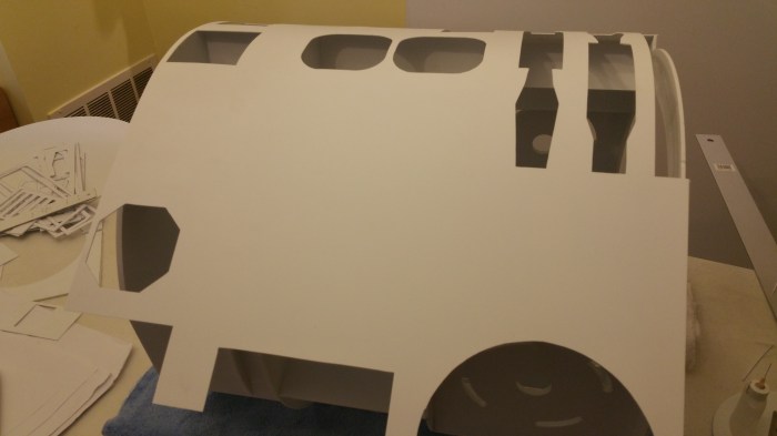
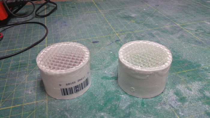
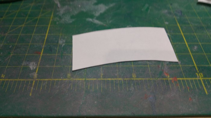
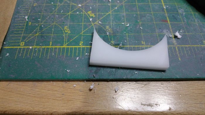
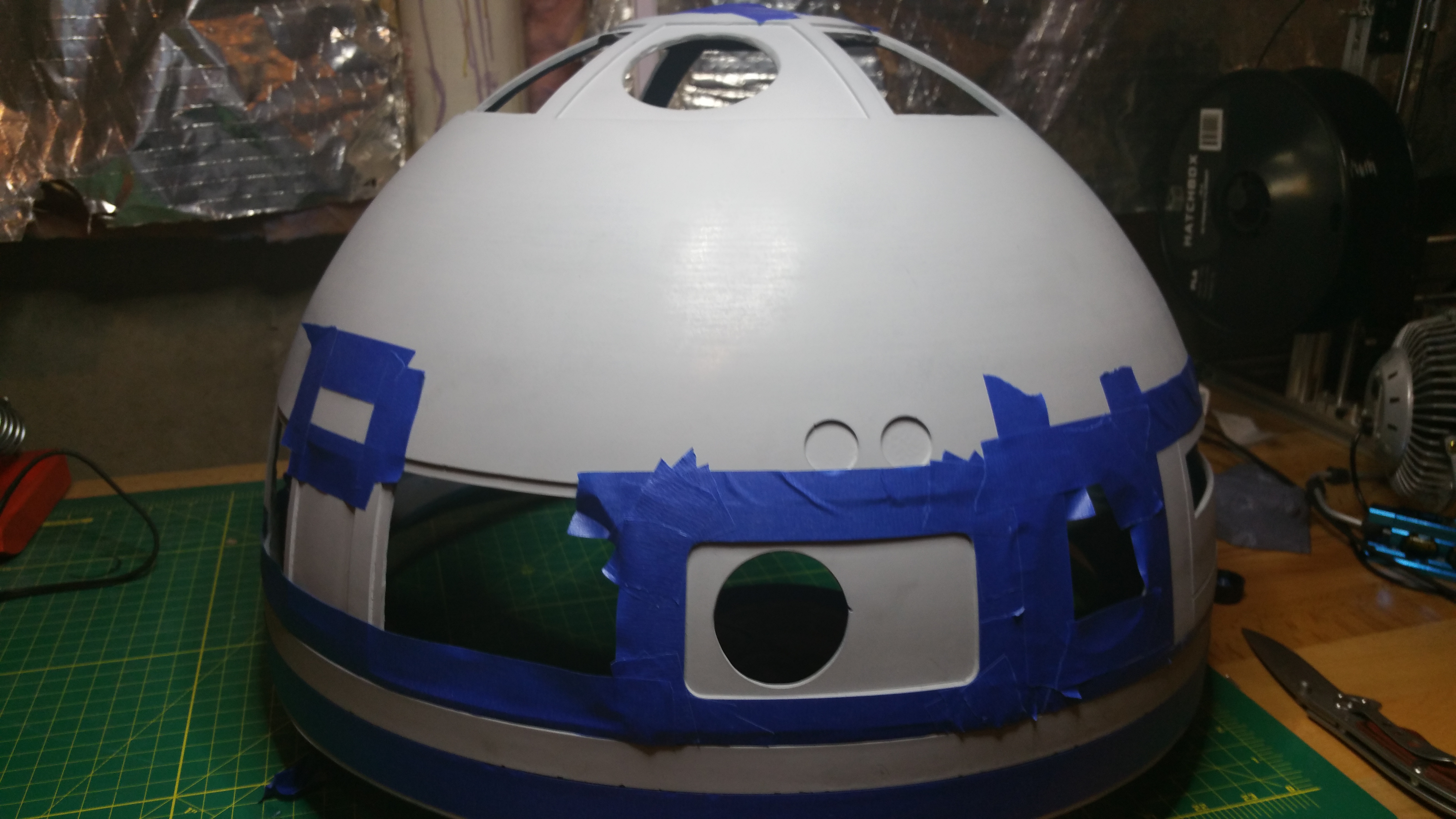
I covered it in tape to avoid splintering of the plastic and to provide a surface that I could easily mark out  where I needed to cut.

20150628_163552Used a dremmel with a cut-off wheel to get it down to size

20150628_163811
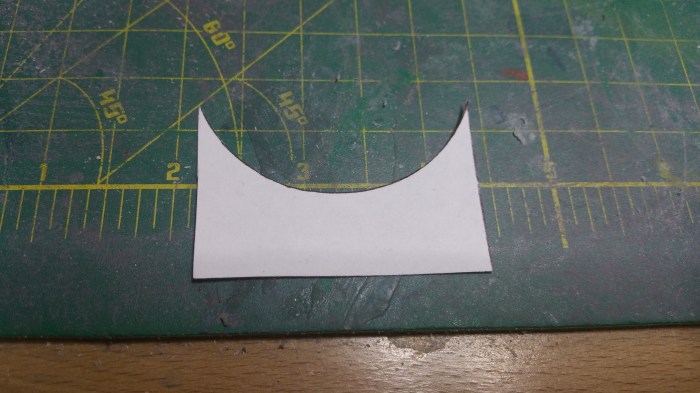
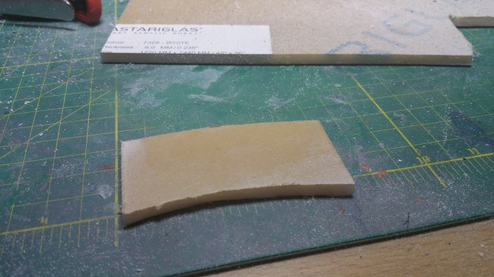
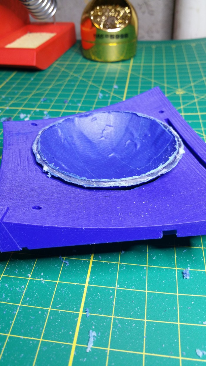
Sill a bit too big. Should be close to flush with the part, so that the whole piece will fit flat to the dome.

20150628_165427

I used a table mounted belt sander to get it down the rest of the way

20150707_172907 - Copy

I painted the inside of the “lens” black to give it a mirror like appearance.

20150708_164547
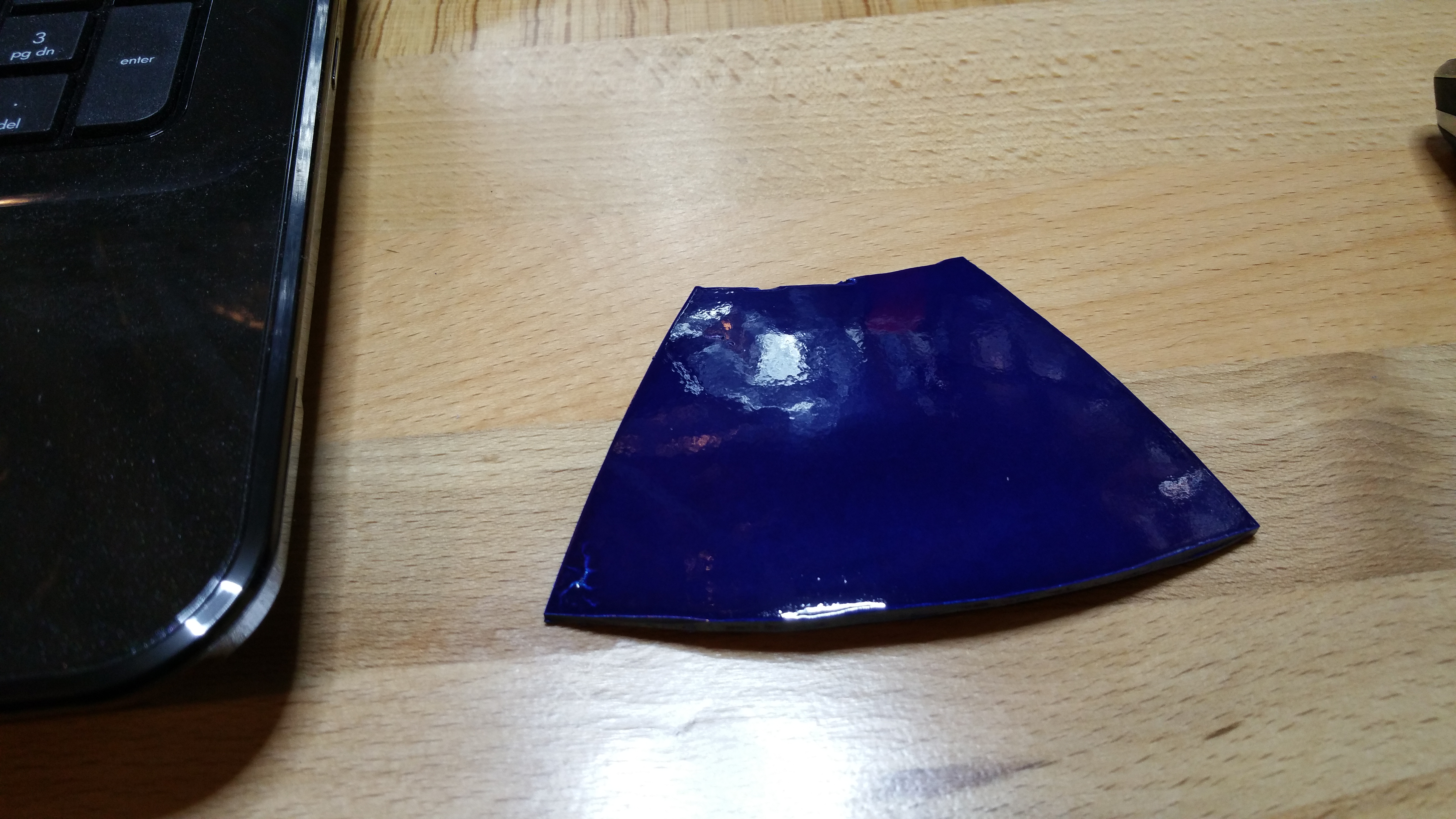
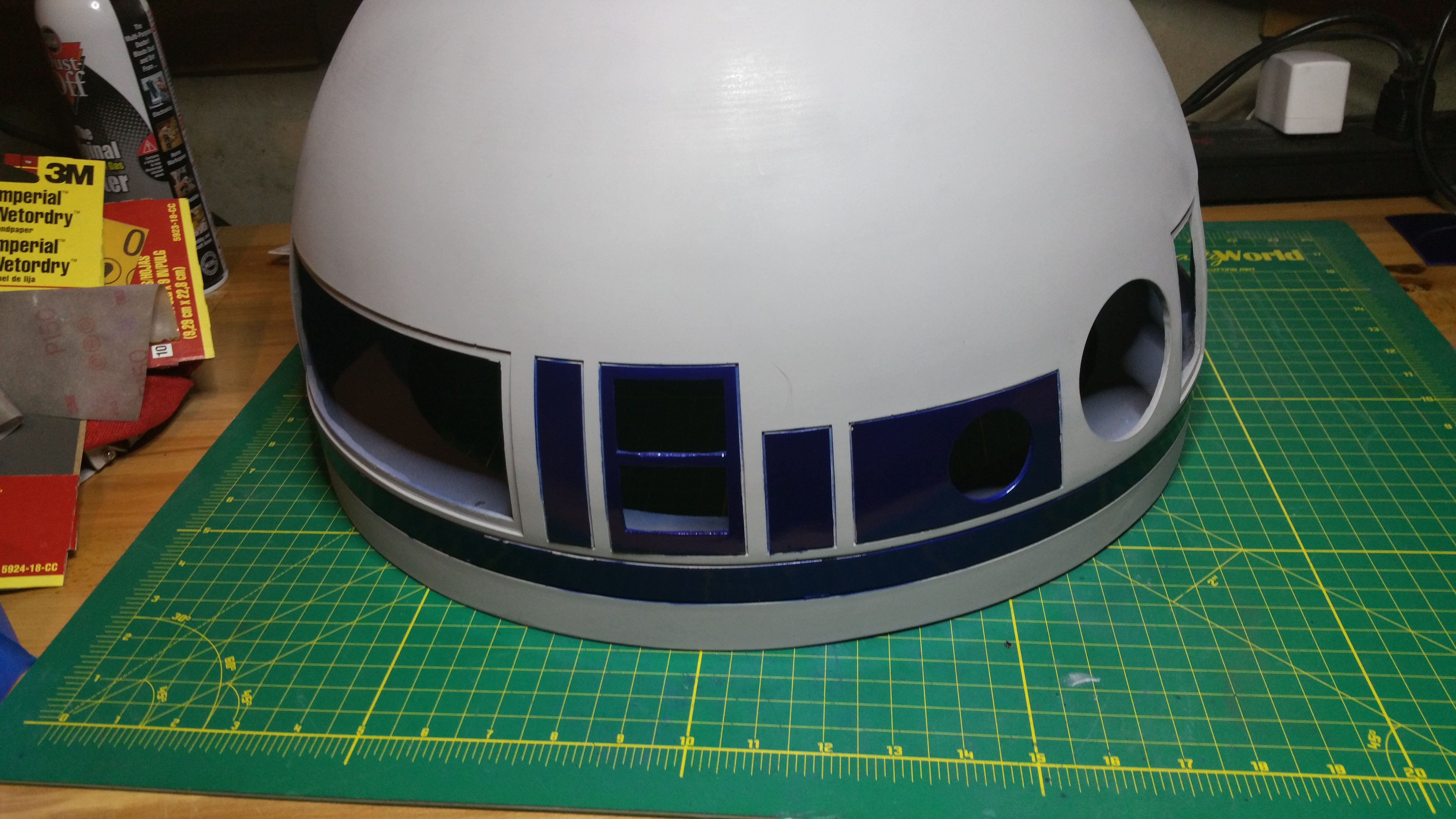
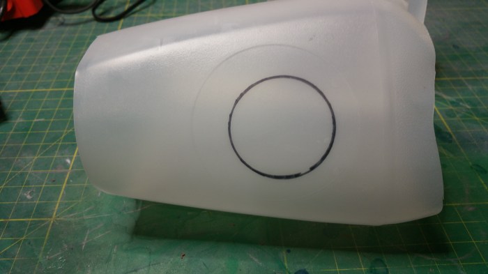
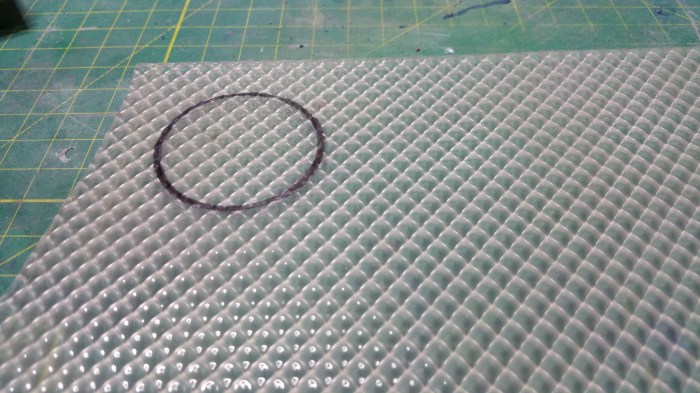
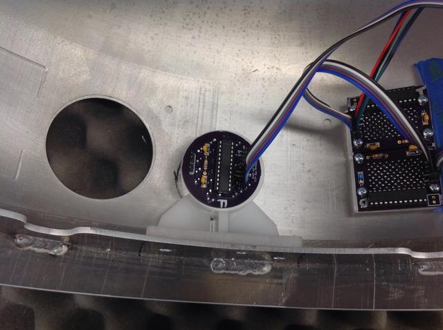
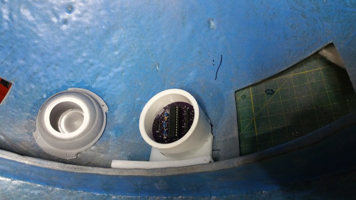
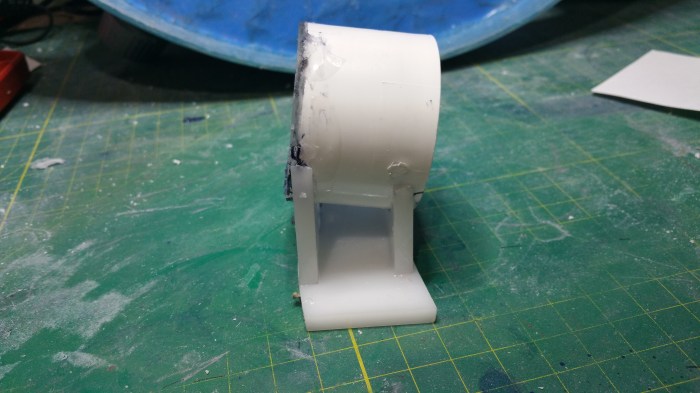
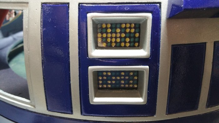
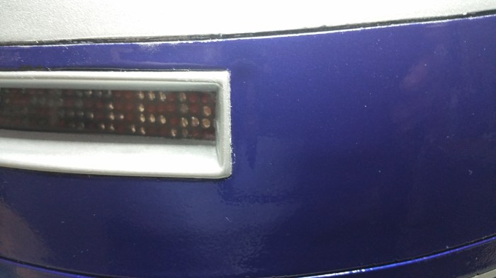
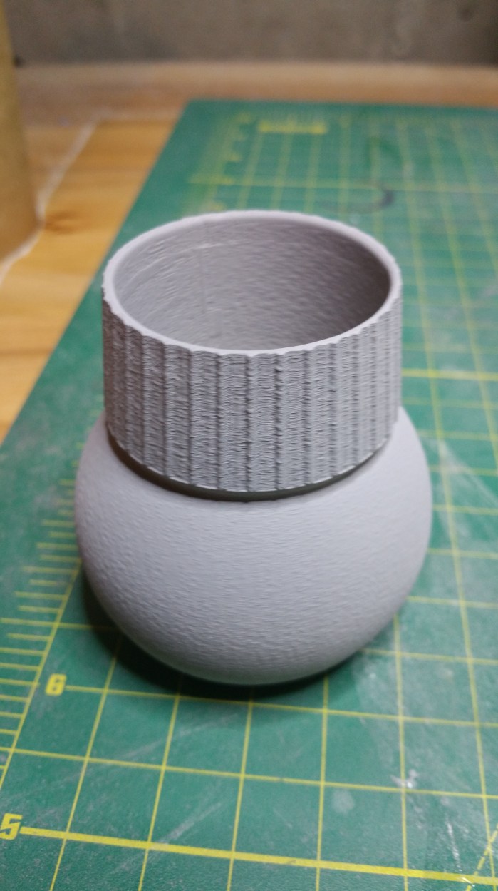
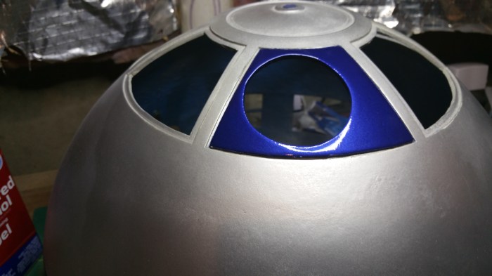
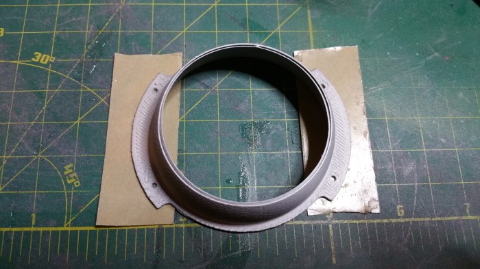
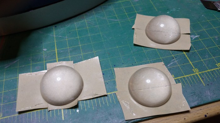
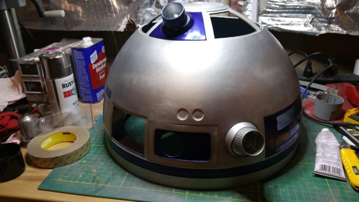
Nice and shiny. Now on to the body of the eye.
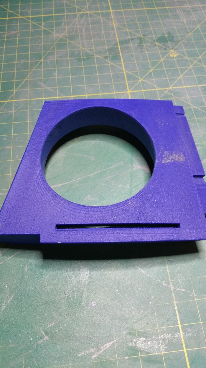
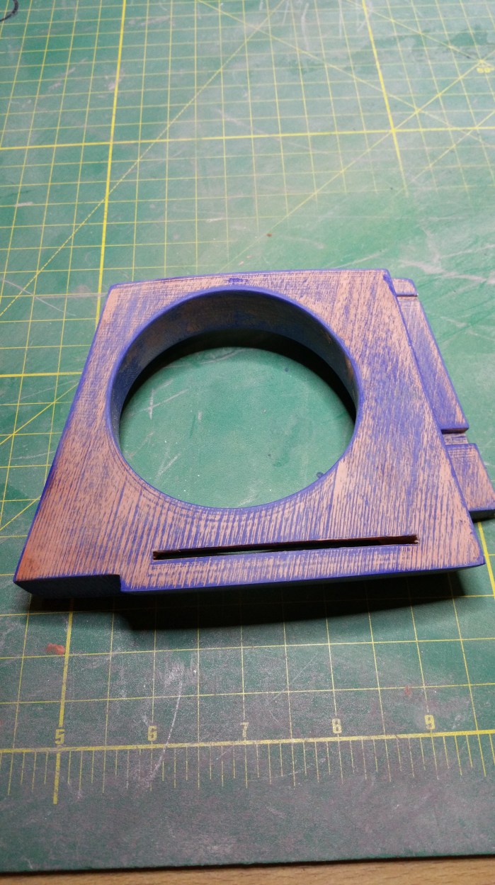
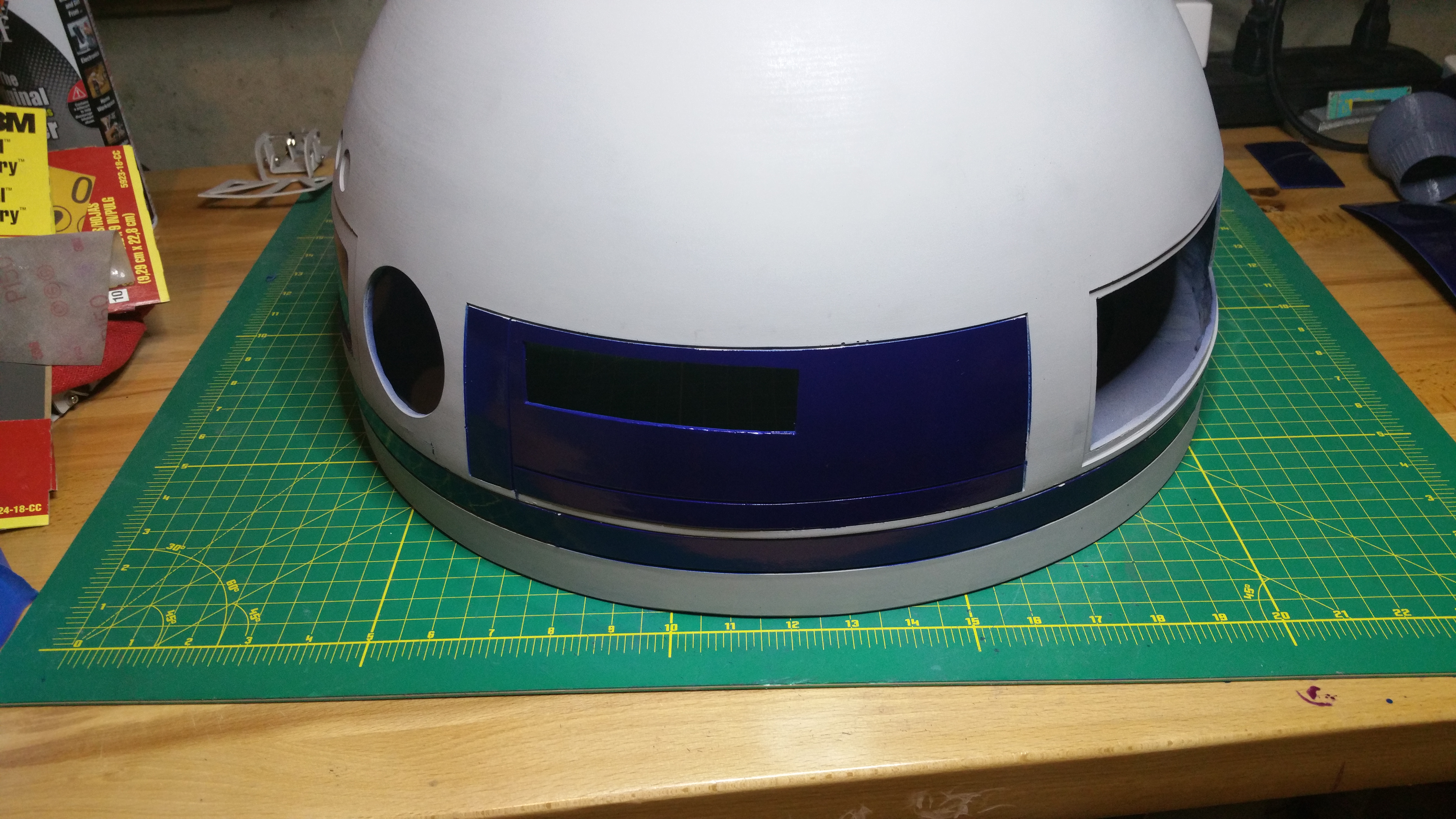
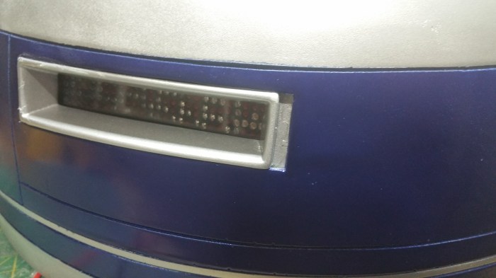
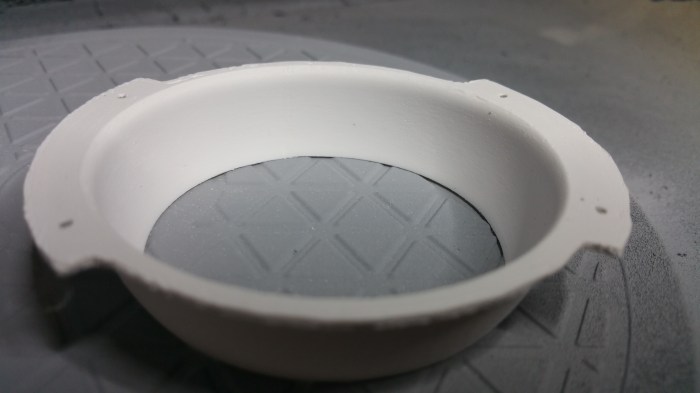
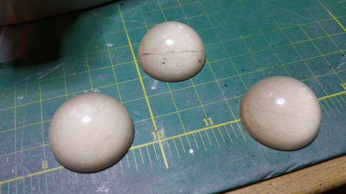
20151119_181333

Its a 3-d printed part. but not one that i printed myself. I got this before i decided to get a printer for myself.


One of the obvious issues with 3-d printed parts is because the part is built up layer by layer, you get “print lines”. You can see that this part was printed with the left side of the part sitting on the print table. The print lines all run parallel to that surface. From bottom left to upper right. And while this part is a really good print, the lines are still there. It is not just a visual line these are actual ridges of  plastic. Since this particular part is pretty simple in shape, and doesn’t really have that much detail it will be a pretty “easy”. I need to fill in those lines with filler putty. The Fist thing I needed to do though was get a different type of filler.

20151119_181523

This is a one-part putty, as compared to the two-part putty I was using on the dome. I’ve got a little bit more time to work with this stuff than with the two part, plus it saves me a step or two mixing up my own filler.

20151119_182522

First pass with the putty, you ca really see some of the print lines I was talking about in this picture.

20151120_113514

After the fist sanding. Starting to knock down the high spots, getting a lot more smooth.

20151120_165252

This is after my first coat of primer. It shows where I needed to re-do some of the work. I hadn’t quite got out all the lines.

20151122_174731

After reworking, got it looking pretty good. Actually looks like a “solid” piece of material now.

20151123_155104

After a few coats of blue. Looking really nice. just need to add a little bit of detail.

20151125_095717

There are two grooves that I need to paint silver. This was a little bit of pain because of all of the angles that I had to deal with in this section of the part.

20151126_180808Finished

Now I have to attach it to the dome.

20151126_181503
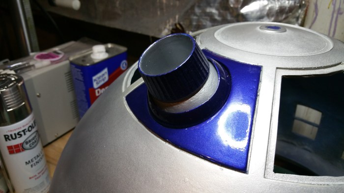
This seems to be pretty good, but trying to find out out the exact position is a little trickier than it first would seem. It turns out, for whatever reason, that in the movies the radar eye is all over the place. Not so much that you would notice it while watching the movie. But when you start looking at it scene by scene, and focus just on his eye, it moves around quite a bit.

I decided to “glue it, and screw it” to actually attach it to the dome.

20151125_093828Using this type of bolt. It’s called a hanger bolt. The same kind of bolt, but much smaller, obviously, that is used to attach couch legs to the frame. The pointy end I screwed into the back of the eye.

20151126_181538

I had to drill through the dome to attach washers and nuts to the other side.

20151128_093443The right bolt went into the piece a little bit crooked so i had to enlarge that hole just a bit.
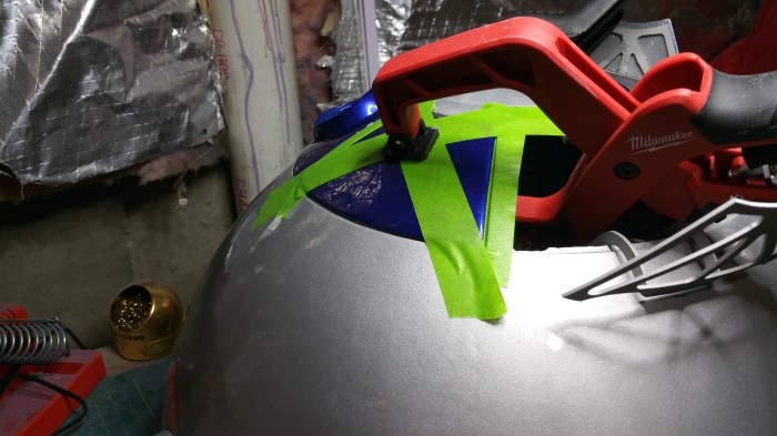
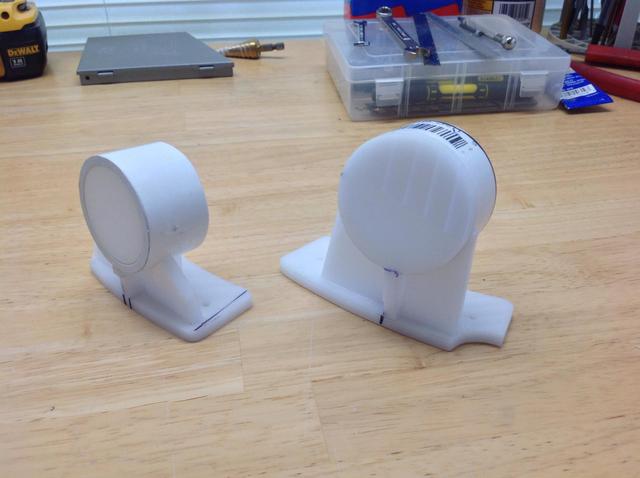
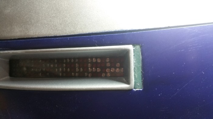
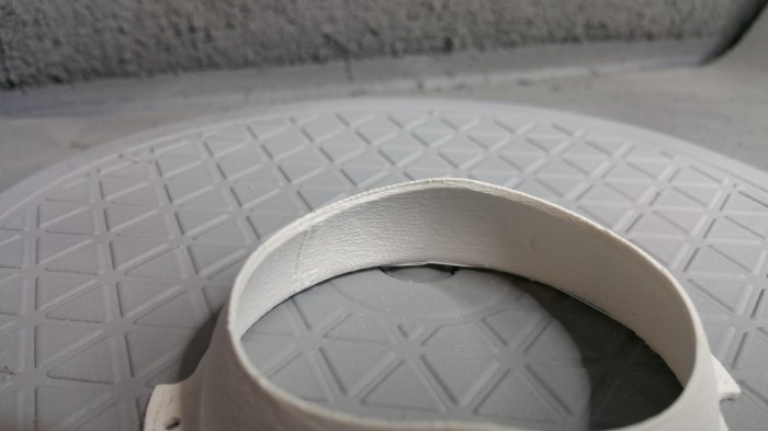
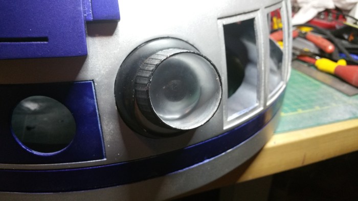
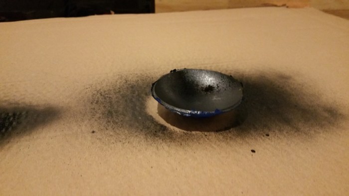
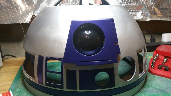
This is the glue I used

20151129_090925

Industrial strength and it dries clear, I have another type of glue that may be a bit stronger, but it dries white.

20151128_101451Attached!

20151129_090851
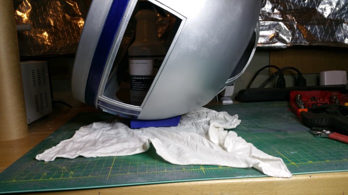
I didn’t have any clamps that were big enough, so this is how he has to sit while the glue sets up.

Next up, I think I am going to tackle the holoprojectors. This may take a bit more time because they are a bit more detailed, and they are going to be the first moving part.

Setback

Sorry it took me so long to update my blog. I hit a bit of a setback and it has taken me a while to get back on track. Unfortunately I will not be able to have R2 completed by the time the movie comes out. Oh well it was a long shot anyway. Life kinda got in the way, as it usually does. Plus I hit a snag with the painting of the rest of the dome.

20150812_170620
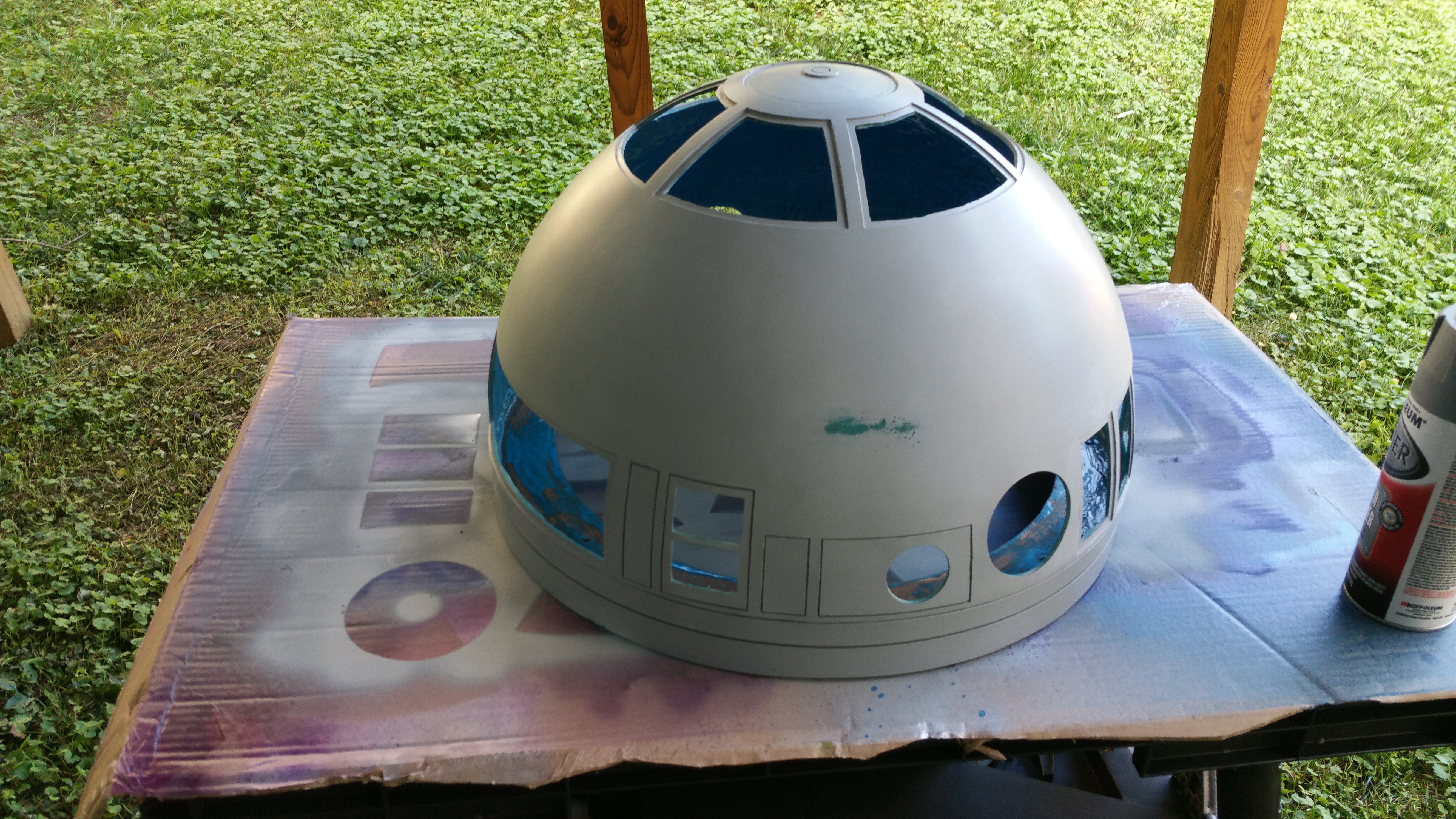
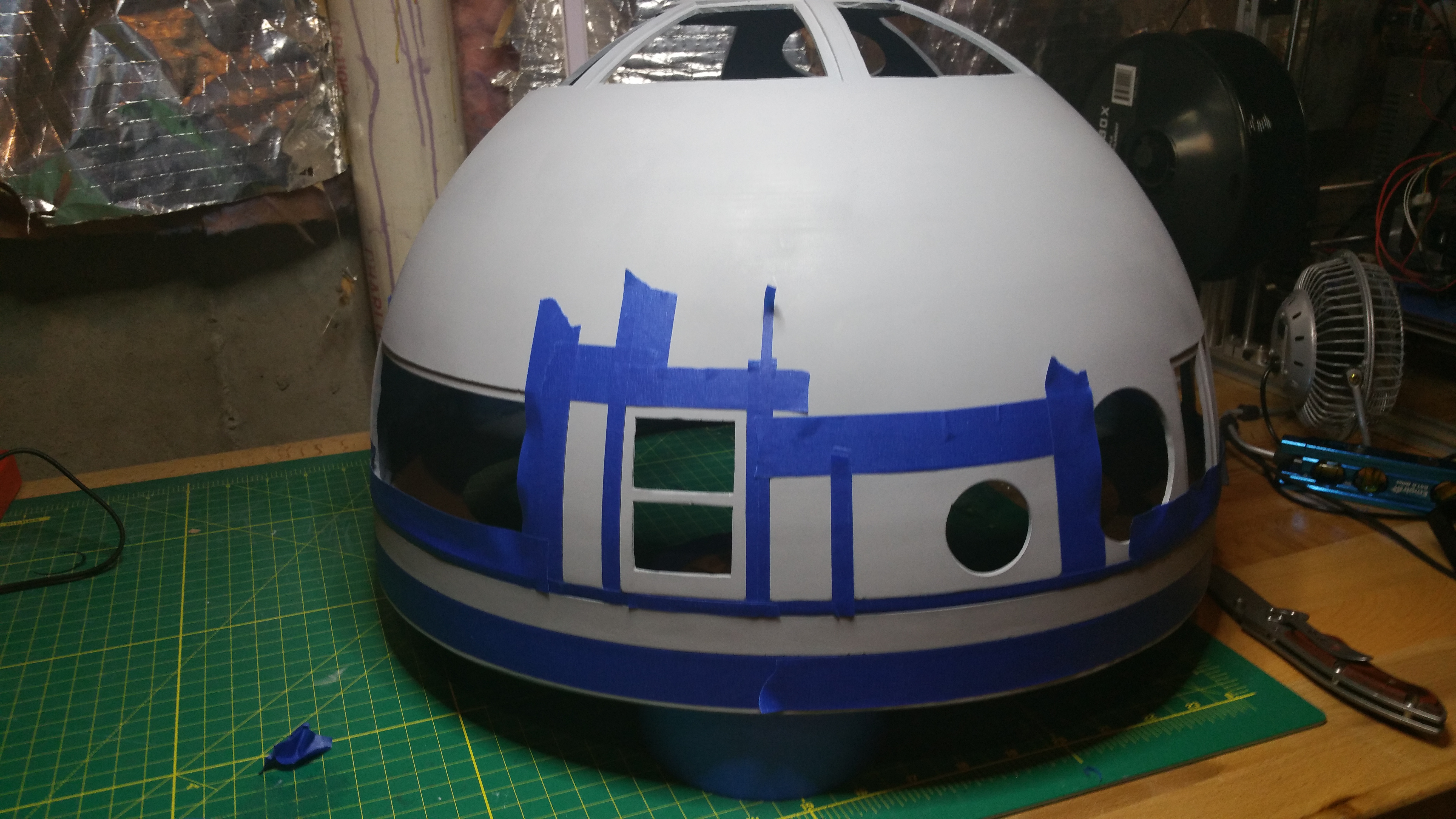
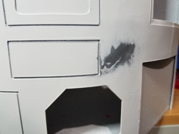
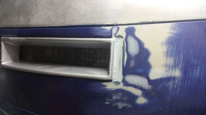
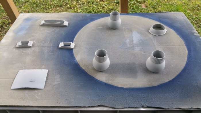
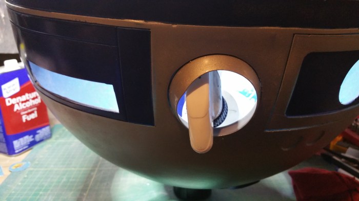
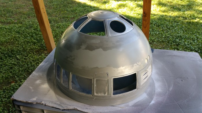
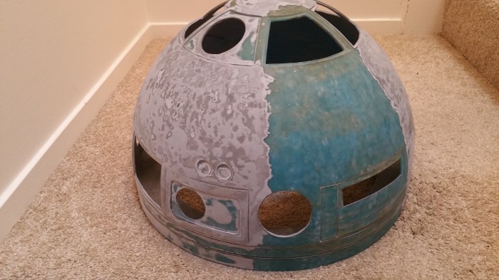
Masked off the blue panels that I had just painted. The first mistake had already happened by this point. I should have painted the overall dome first. Not realizing this at this point I put my first coat of silver.

20150812_174929  
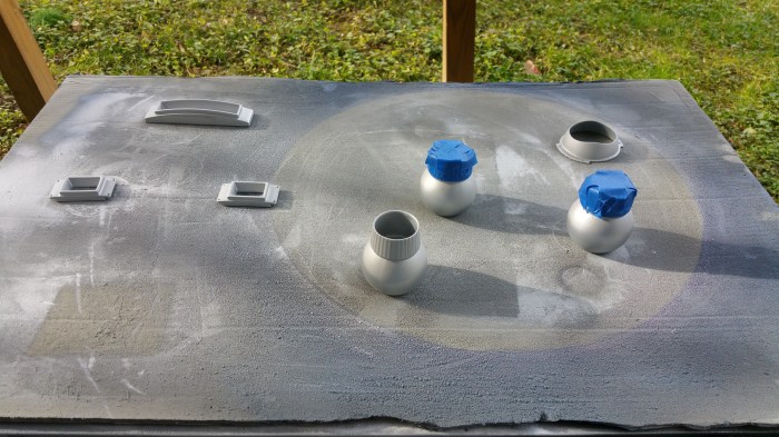
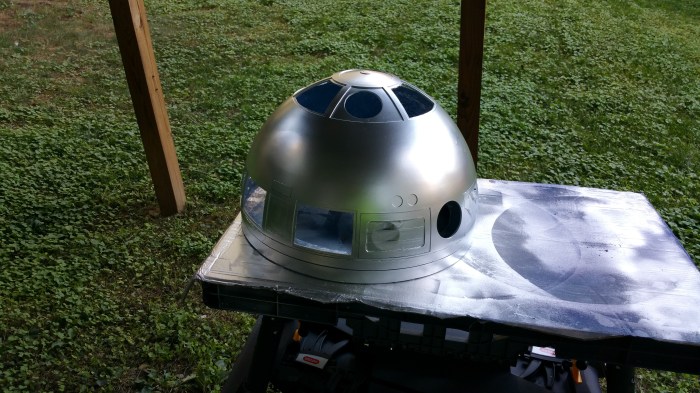
This is actually the third coat of silver. I did not take any pictures of the other coats because I wanted to wait until the final coat to get a good picture. It was about this time that I started to realize that this was going to be harder than I thought it would be. It may not look like it here, but there is all kind of issues I was having. I put it on too think a one place so I had a paint run. And it was windy so I had some small foreign objects that had blown on to it. So I had to fix those issues with sanding, lots and lots of sanding. No big deal, mistakes happens.

Evil


20150822_112953
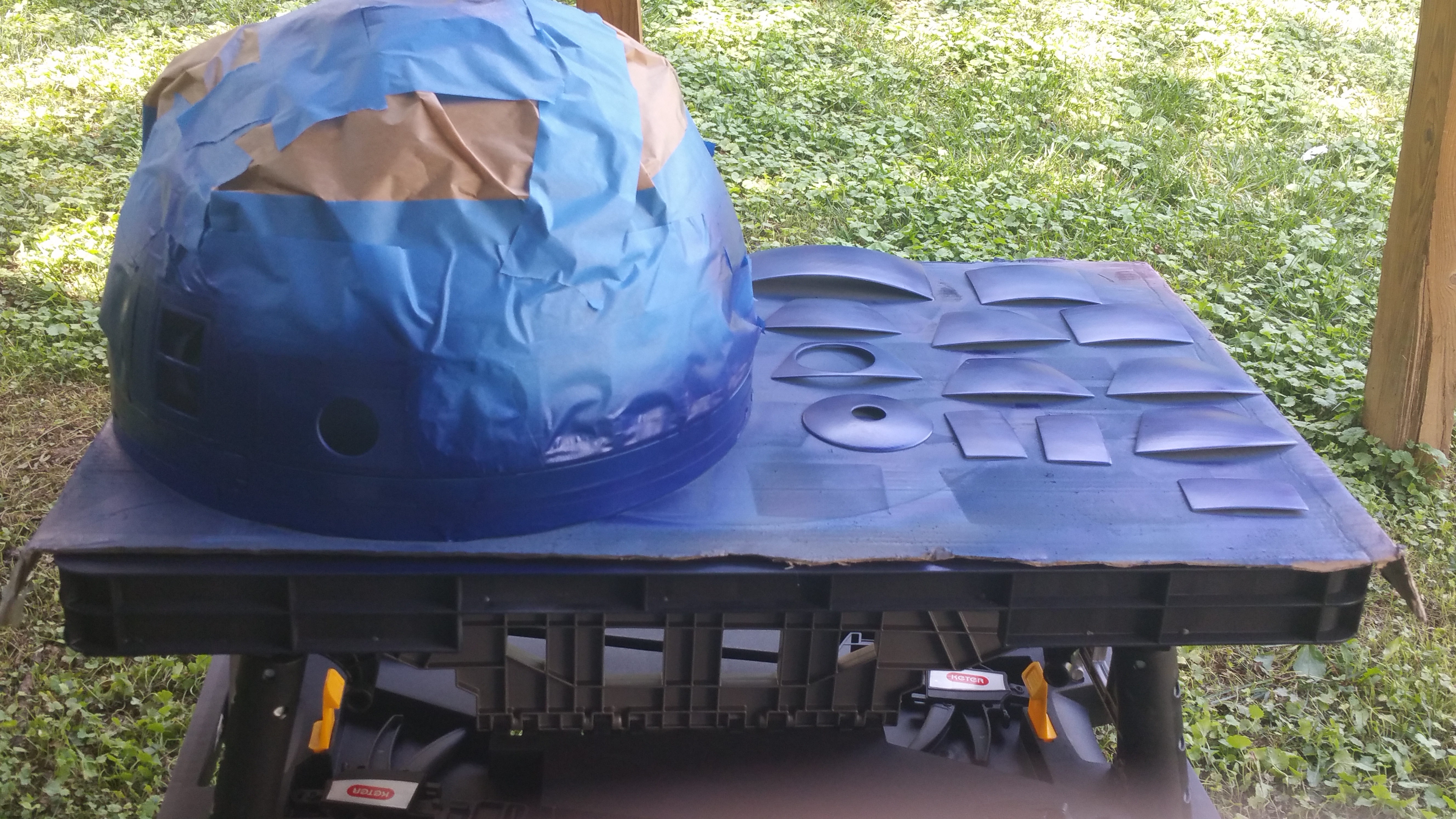
Ready to try again, But this time before I started, I put up some plastic. I am actually doing my painting under our deck so I just stapled some plastic sheeting to the wood. Making a make-shift paint booth.

20150828_115234

I also found a box that I used to elevate the dome off the table a little bit, I don’t know if it helped improve the paint at the bottom at all but I figured that it couldn’t hurt. I also slowed down a little bit making sure to not get any runs.

20150828_115726
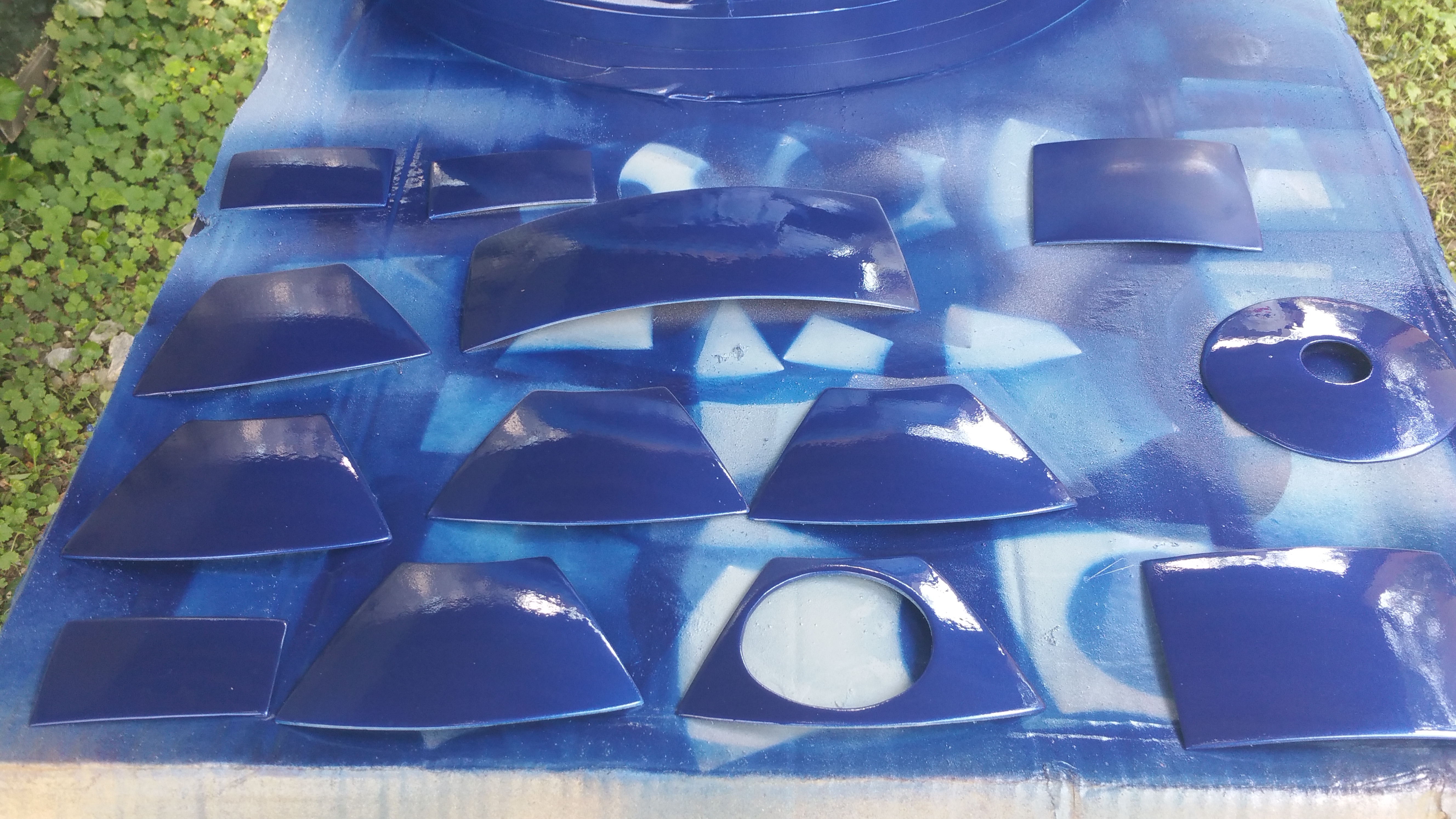
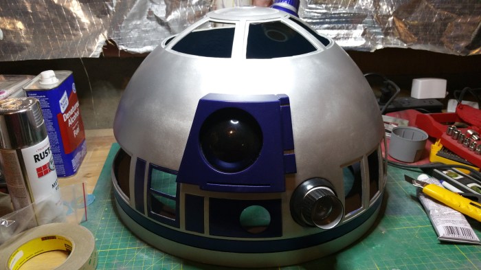
Yeah! Looking pretty good, finally.

Until I tried to touch it. Every time I did, it left streaks. No mater how lightly it was touched. I thought, OK that just means I will have to put a clear coat over it. No big deal, right. I was planing on doing that anyway.

Unfortunately I don’t have a picture of the outcome, (I was starting to get REALLY frustrated) apparently there is an issue with some combinations of metal colored spray paint and some clear coats. Instead of it creating a nice tough glossy finish it will turn it grey. Something about the clear coat taking all of the reflective nature of the metallic pain out.

200

AARRGGHH

I had some research to do.

I looked at the Astromech forums to see if I could get any ideas, but it can take a long time to sort through those boards, and it seems to me (I could be wrong) that about 90 to 95% of the people on there have an aluminum dome so they would not have this issue. And the people who do have paint their dome either figured out how to do the paint on their own, or they use a paste/wax product call rub-n-buff. I actually tried rub-n-buff before I started painting and I just could not get it right. But there are some domes that look absolutely amazing using it, I could never get the technique down.

I finally tracked down a possible solution. Future floor wax. It turns out that scale model builders run into this issue a lot. Especially the guys that do military and air craft scale models. Its actually a water soluble acrylic floor coating developed for linoleum floors. Since it is acrylic it will dry clear and will not yellow over time. And since it is water soluble, if I have any issues, all it takes to take off is ammonia, or Windex.

So I put another coat of silver on. Another great job without a picture.

20150828_184814
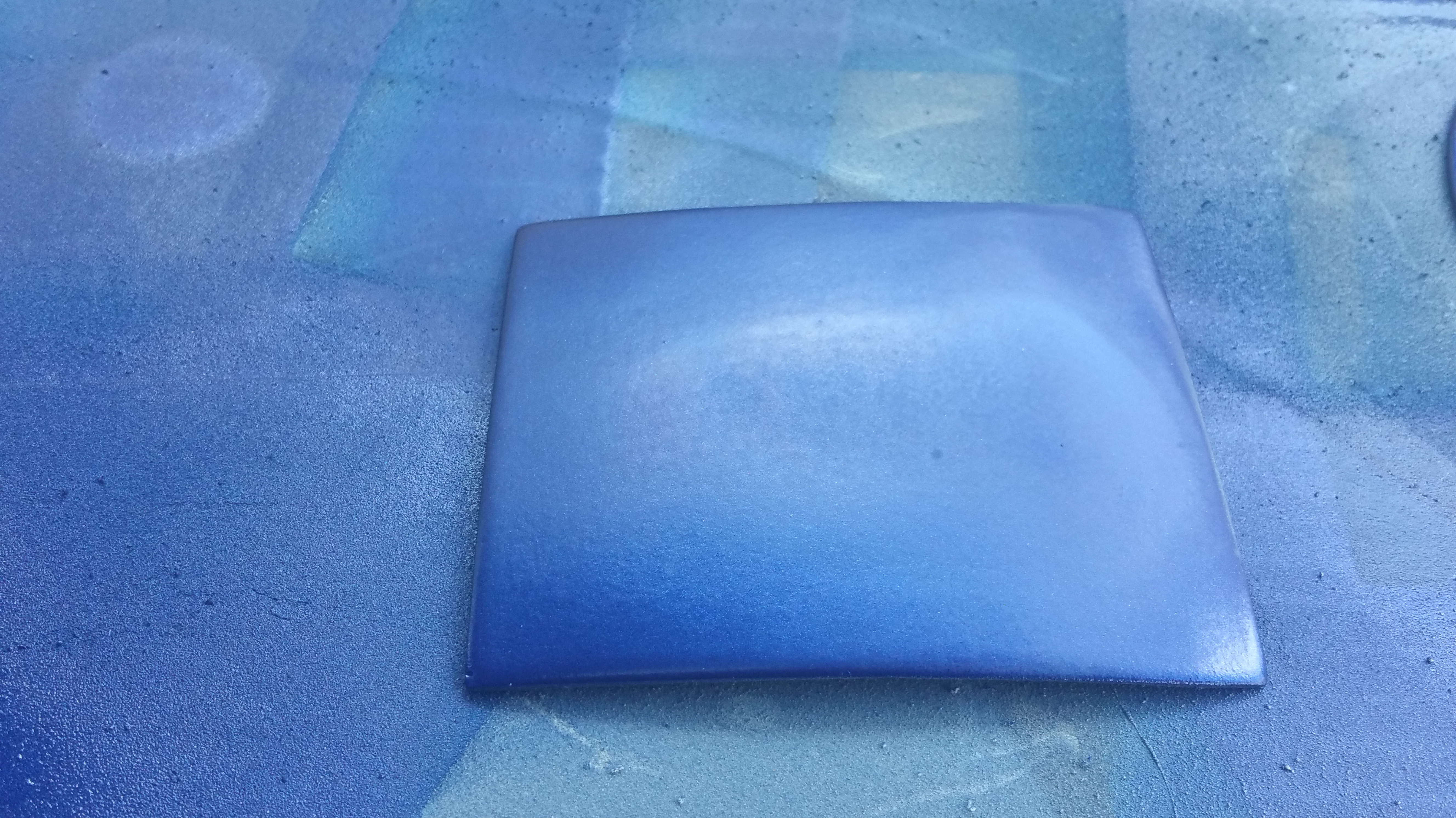
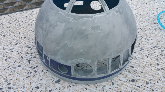
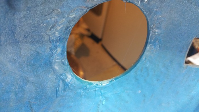
This is the while I was waiting for the stuff to dry. I was pretty nervous because I wasn’t sure if the milky part would go away or not. It did.

20150829_155217This is after it dried, looks pretty good.

But again, the camera is not picking up what was very obvious to the naked eye. Brush stokes. OK, I thought, no problem I can just take it off with some Windex and try  again. So I tried again. And again. And again. I tied regular brushes, foam brushes, sponges, spraying it on. Nothing worked. There was always some very obvious streak, or brush stoke or something.I got it the best I could and figured it’s probably not that bad and I was just being hyper critical of it.

Remember when I mentioned my first mistake at the beginning. It was at this point that I figured that out. I had left the same masking on through this entire process. Probably 2 to 3 weeks. That is WAY too long to leave painters tape on. Not only did the blue paint chip as it was coming off, it left behind tape residue that I just could not get off.

Cameron

In the gaming world there is a phrase that is used called “Rage Quit”. It means just what you think it would. You get so frustrated and mad at an outcome that you just quit, immediately, and just walk away. That’s what I did I walked away.

For a month.

When I decided to start up again I realized I actually had two problems. One being the messed up blue paint. The other was something that I had noticed about 3/4 of the way through getting the silver paint right. I had put on so many layers of paint that is was getting noticeably heavier. I wanted to get all of that paint off and just start over.

My first option was to sand it all down. That was not going to happen. It would have be by hand because of the curves. and just judging by the spot sanding I had done earlier in the process, it would take a very long time and would be pretty tiring. I had the idea to try acetone, but I was not sure how that would affect the dome itself. I e-mailed the guy who actually made the dome and asked him. He said that yeah acetone would work and would not harm the dome itself. But he said that he had tried to clean paint off of other objects with acetone and it ended up being just a big mess. What he suggested was to try soda blasting it.

Soda blasting is just like sand blasting, but instead of sand you use bicarbonate of soda. Baking soda. Its a much gentler method of removing paint. I’ve seen videos on-line where people are soda blasting their car and it does not damage either the chrome or the glass. After researching for a bit, I realized that I could get the equipment needed to do the actual blasting relatively cheaply, but because of the nature of soda blasting, the air compressor needs to be pretty beefy. I didn’t want to buy a much bigger air compressor than I would need for 99% of the jobs I would probably use it for. I then realized that I have access to a industrial sized air compressor at work. The only down side would be that I could only use it on the weekends when no one would be using it. And as I would later realize that there would be no good way to capture and reuse the soda, which would mean I would have to keep buying more media.

20150919_110404
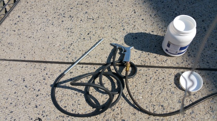
This is the equipment, basically an air gun with a rubber hose attached to a feeder pipe that you stick into the soda.
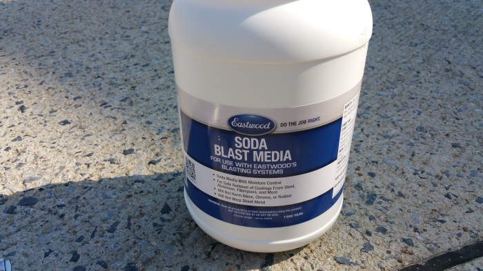
20150919_110321Soda media

20150920_095049

20150920_095058After first time. I’ve probably taken off one or two layers at this point. hadn’t started on the blue that much yet.

20150928_172742

20150928_172800
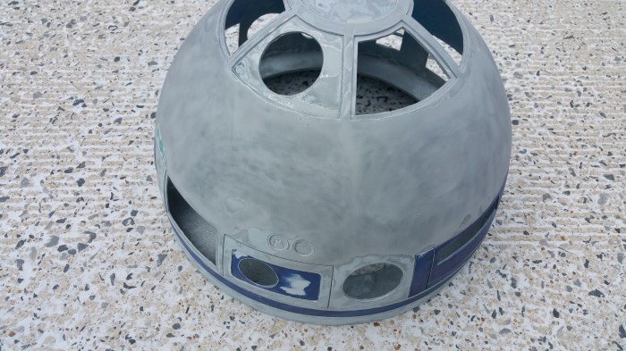
After the second weekend. I went through a fifty pound bag of media but I was able to take off a significant about of paint. Started getting down to the bare dome.

20151024_200044

20151024_200031After the third and final weekend.

Tina went with me on the last trip and was able to take some video.

20151026_162544
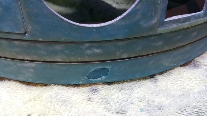
When I was stripping the paint I accidentally dropped the dome on a rock.

20151026_163328
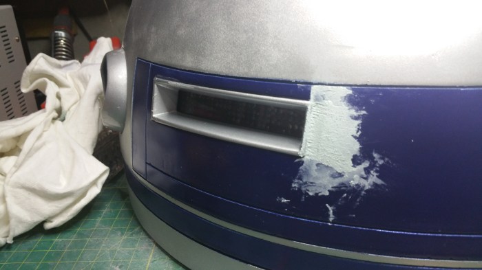
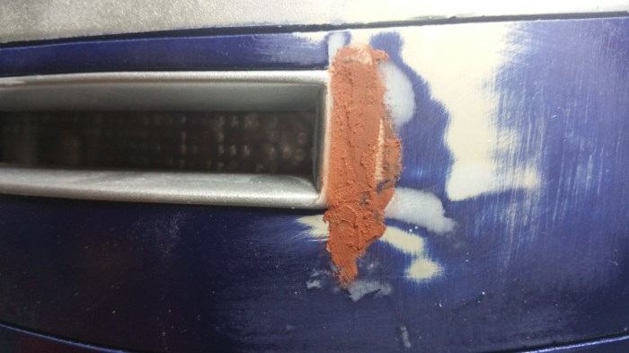
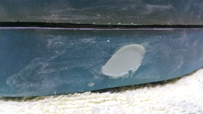
Nothing a little body filler cant fix

So time to start the painting process over again. This time I got a different type of spray paint, more of a professional type, as compared to some from home depot.

20151031_140845

20151031_140911
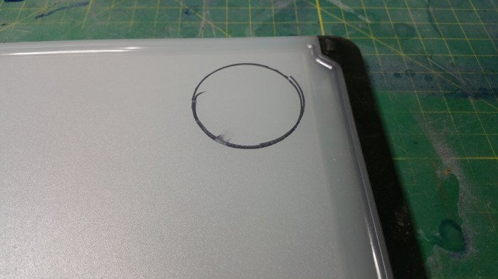
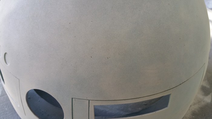
After the first light coat of primer all of these pin holes from the forming process really popped out. It wasn’t a surprise I saw them as I was stripping off the paint. This scratch coat was just used to highlight them so I could then fill them with putty.

20151103_171300
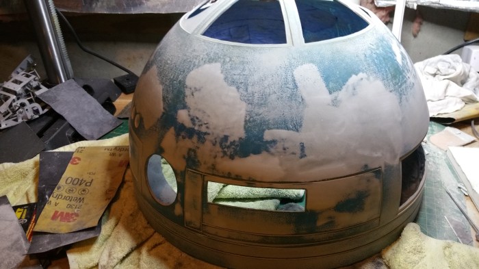
Holes taken care of, now to start sanding…again.

20151110_173844

20151110_173833
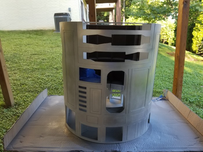
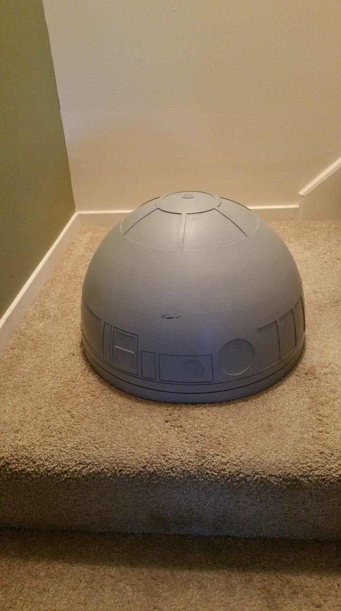
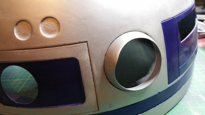
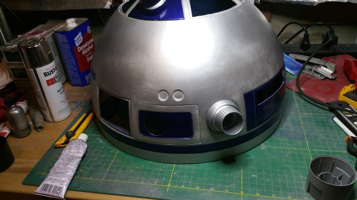
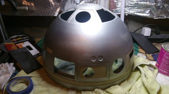
The new silver is on, It’s not perfect, and it’s not as shiny as it was before, but I’m fine with that. But if you look at R2 during the original trilogy, besides the last scene in the throne room, he is pretty banged up. I actually like this better than the original paint job. to me it looks more like actual metal. Also notice that I painted the silver first this time.

20151111_200755

20151111_200741
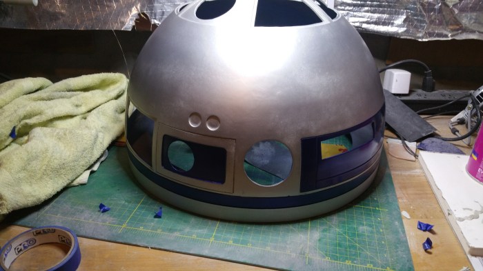
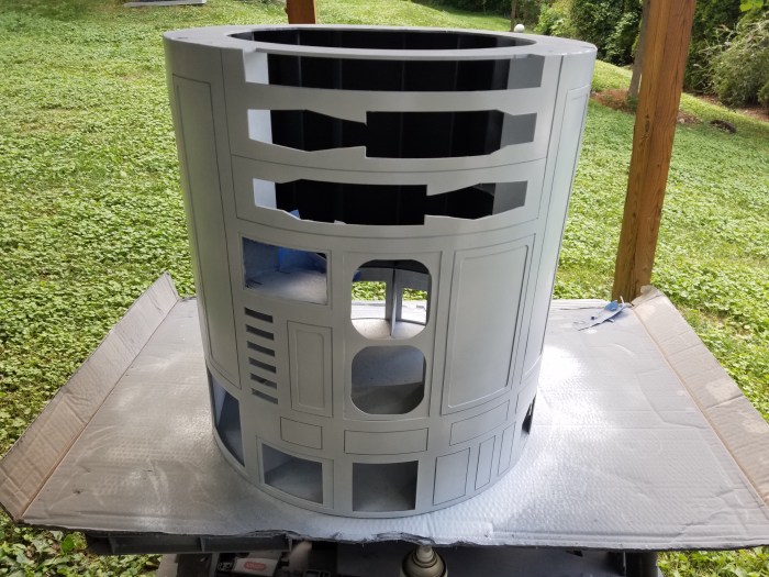
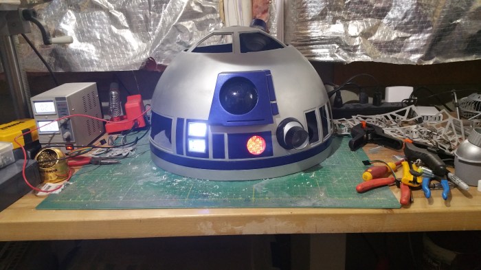
And here it is. I am finally back to were I was 3 months ago.

Several times throughout these past 3 moths I was asked, “Why don’t you just take it to a professional to strip it and paint it?”  Yeah, I could have probably done that. But I really want to do this as much as possible by myself. I’m going to make mistakes, and I am going to get very frustrated. I’m going to get pissed off and confused. And it is going to take a lot longer than I want it to. But at the end of it all I want to be able to look at it and say I made that, all of it.

About those updates…

So obviously I was wrong about more updates. It turns out that just the opposite happened. Too much stuff going on, not much time to do an update. Sorry about that.

The 3d Printer is up and working. It was a bad board that was causing me issues when I first set it up. I have learned that there are SO many variables that come into play when trying to get a good print.

The print bed needs to be absolutely level. The temperature of the “hot end”. The hot end is where the plastic filament is melted and comes out of the nozzle. As apposed to the cool end which is what feeds the filament into the hot end. The Temperature of the hot end has to be high enough to melt the plastic, bit not too hot. If it is too hot then the plastic comes out stringy. Different types of plastics melt at different temperatures. Different colors of the same type of plastic may also require different temperatures. Same plastic, same color, different manufacture, may require a different temperature. Also the print bed needs to be heated to different temperatures depending on the type of plastic as well. These temperature changes may be as little as 5 degrees. It also matters how fast the plastic is extruded from the nozzle. How fast the extruder itself moves across the print bed is important as well. So it can take some time and a little experimenting to really dial it in. I’m still in the process. The prints that I am getting are OK, but they could be better. I had taken some pictures of this process but for the life of me I can not find them on my phone. All I could find were these

Printing of a cube made up of movable gears

20150803_061808

Skull

I will try to get more pictures for the next update.

R2 Progress

Things are coming along on the dome I had actually hope to have a majority of it done by now but playing with the printer kind of set me back on this front.

20150717_183227

Rest of the panels cut out

20150717_175655

Very dirty job

20150718_15011120150718_150119

Dome openings cut out. The dome itself turned out to be very easy to cut out. The carbon fiber panels I cut out will cover most of these openings.

20150717_175624

Like this.

Now comes the first part of the build that I absolutely no experience ( the first of many I am sure). Auto body work. The same material/techniques anyway.

Apparently when the carbon fiber panels are made, and to a lesser extant the dome itself, bubbles form. The guys who make the panels do everything they can to reduce them, but there really is nothing to be done, there will be little pits that end up in the final product. So to combat this you use body filler. You want these parts to be as smooth as possible because when you paint them, the pits will be VERY visible.

20150726_155005

Like this

20150726_155259

Spread it out on a clean surface, just a little at a time because this stuff will harden pretty quickly.

20150726_155338

Once you add the hardener. The more hardener you add the quicker the dry time.

20150726_160348

You can start to see some of the pits after the filler is spread on

20150728_213625

Sanded smooth, you can really see them now.

20150728_213635

closer view.

20150731_162632

Laying out to begin painting

20150731_165124

After Primer and first coat. The painting technique that was suggested on the message boards to get a really close to screen accurate color is as follows. Lay down a base coat of metal colored paint. over the top of that add a coat of purple anodized color and on top of that a coat of blue anodized color. The purple and blue anodized paint will let the base paint show though. So in theory it will really look like metal. The primer that was also suggested is a adhesion promoter. This will give the paint something to “grab” on to besides just plastic. It is also clear. That is why I did not see this until after the base coat was on.

20150731_165132

MORE PITS UUGGHH. You can really see how much they show. I obviously did not do something right.

There were three panels that were OK so I decide to keep going and sprayed on the first coat of purple.

20150731_172745 20150731_172753

This kind of paint is VERY thin, I was not expecting that at all. It ended up looking really bad.

20150731_172703

I had one of these that looked better than the rest so I decided to try to put on the blue coat, to see what it might look like.

20150731_173633

The blue seemed to be even worse than the purple. So I decided to just give up at this point and start over again.

20150801_100417

More filler, more sanding.

I decided that i need to get the correct painting technique. Unfortunately I didn’t get any pictures of that process.

20150802_191110

I think i got it pretty close, maybe a little on the dark side( no pun intended). I’ll have to work on that. I also decide to do both the panels and the dome at the same time. This way the final color will match. If i were to do the dome on another day, the colors might be a little bit different depending on temperature and humidity.

20150808_093944

Prepping Dome

20150808_094622

Changed Primer, no longer clear so I can spot any issues early.

20150809_112833 20150809_112847

Masking off the parts I don’t want to be blue

20150809_115517

Painting blue layer

20150809_150311

After adding clear coat

20150809_150301

Looking good

20150809_150326

Except this one piece, not sure what is happening here, will have to re-do this one.

20150809_192731

Yeah i definitely like it better this color.

20150809_193424 20150809_193434 20150809_193442

Dome turned out pretty good as well. but there are a couple of touch up spots I will have to go back and fix.

20150809_193737

With panels in place. I still need to paint the rest of the dome in a metallic/aluminum color

To-do list for dome

Paint rest of dome

Print out/Paint Holoprojectors

Mount hinges for panels

Install electronics

I have been thinking and I might be able to get the whole thing complete by DEC 17. Its not my goal, I don’t have any set date in mind that i want to be done by. But if I can get it done by then it would be pretty cool.