It’s finally time to install the movable panels. This actually took quite a while to do, because at this point everything starts to tie together. So the first thing I needed was to build the domes’ “brain”.
I decided to go with a system designed by a guy on the Astromech forums by the name of CuriousMarc. It called a MarcDuino. It is powered by a Arduino similar to the mini computer used to control lights. It’s a pretty powerful board, that combined with an Iphone app, that he also designed, can control pretty much everything under the dome.

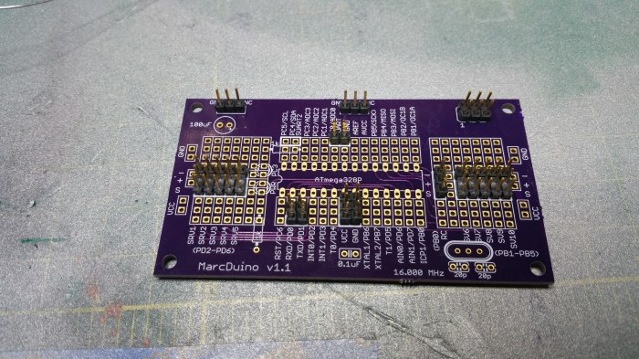
This is the “blank” board. As you can see this is version 1.1. There is a version 2.0 but it’s not DIY friendly. And although there are some upgrades to the 2.0 board, there is nothing that I absolutely needed.
First thing I do is solder on all the connectors.
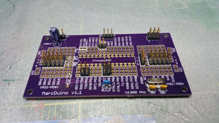
Next is the capacitors.

Resistors

L.E.D.’s

And Finally the Arduino itself. I usually solder my boards in this order as much as possible. With the most heat”sensitive” components last.
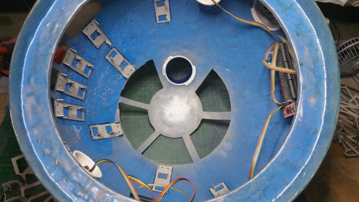
Now onto the dome.
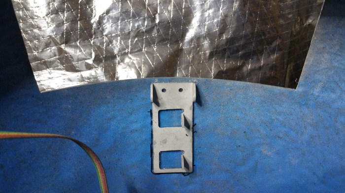
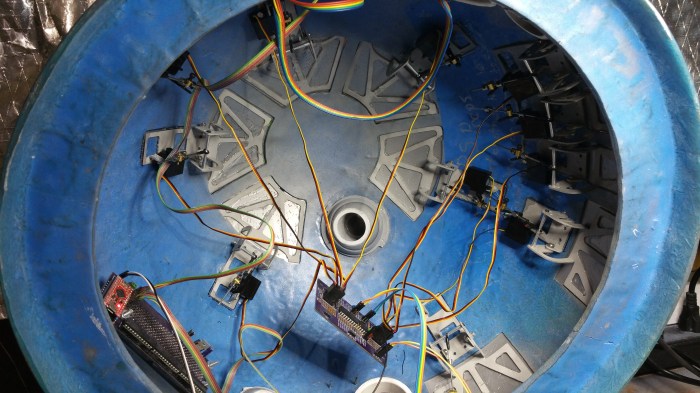
I decide to use hinges that the maker, another forum member KevinHolme, calls the Ultimate Hinge. 
They are very nice hinges. They will allow the panels to open up to 90 degrees. They also have a lot of surface area in order to allow me to glue the panels to the hinge.

In order to make the hinges fit in the hole I needed to enlarge them just a bit

After that I marked out where each one will end up going. This kinda made me a bit sad because I realized that I would be covering up the quote from the guys that made the dome.
First one done. I found it easier to both mark and glue them if I took the hinges apart.
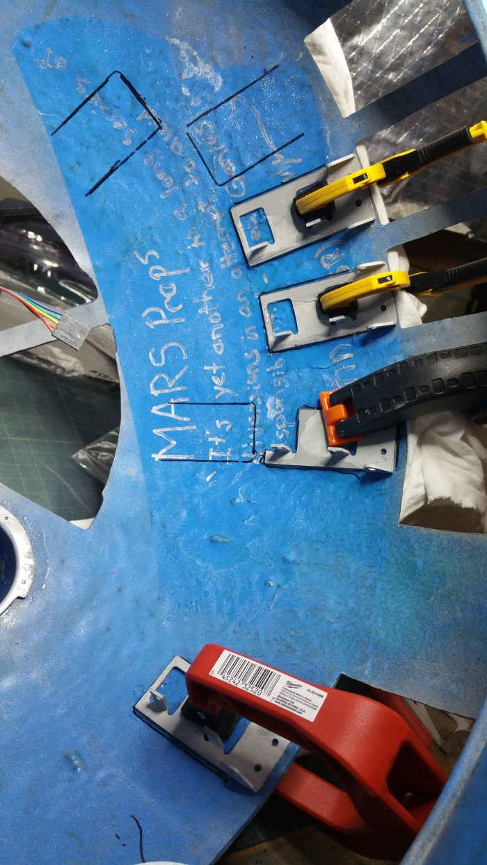
Because the glue I use takes 24 hours to fully cure, this took a little while. I think almost a full week. I “only” have 11 panels, but because of the shape of the dome and the size and shape of some of the holes I could not use all of my clamps at once.
Two more to go, I started to realize how crowded it was going to get in here.


After all the the hinges were glued I attached the second parts. The nice thing about these hinges is, since they are made of aluminum, I will be able to tweek them a little bit in order for them to open and close correctly.

In order to attach the panels to the hinge itself I need glue them to the hinge. I obviously didn’t want to glue the panels to the dome itself so I put some masking tape around the openings.

Put on a copious amount of glue.
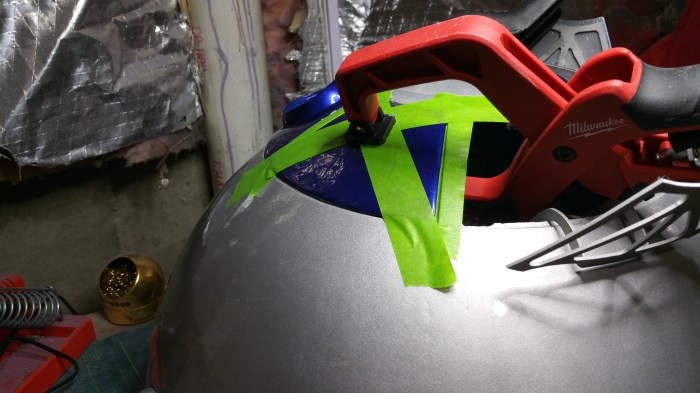
Align panels, and clamp. Again, because of such a long dry time and physical limitations it took another week to complete putting on the panels.
Panels on and power applied to the lights. This is the same video put on my facebook page.
Second video I did not post, showing off the back of the dome.
At this point I could have stopped and called it a pretty successful build. But obviously I did something with those hinges that took so long to install. Next step install some servos.
What is a servo?
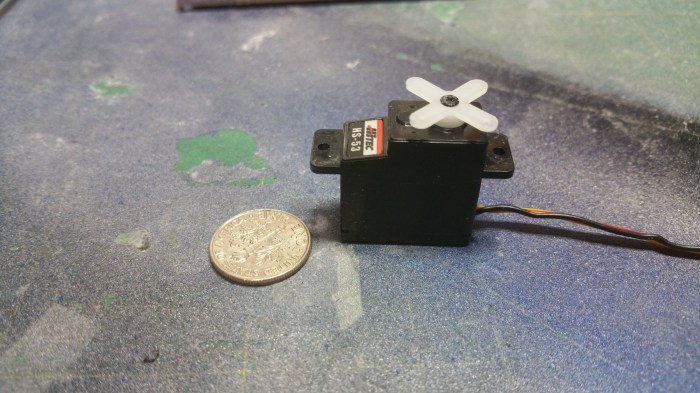
This is a servo. Servo is short for servomotor. It’s kinda like a DC motor that can be precisely controlled. Instead of just spinning around and around like a regular motor, you can control exactly where the motor will stop.
Like this. This servo is connected to the MarcDuino I just built. I can control precisely where the motor stops and which direction it spins.
The other board red circuit board that is also hooked up to the MarcDuino is called a WiFly.
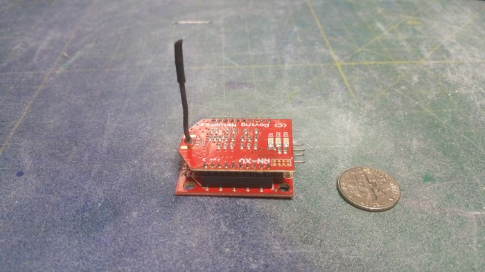
It is a WIFI radio.

I hook it up to the MarcDuino so that I can control it through the App R2 Touch
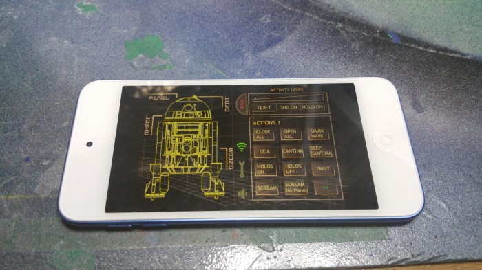
Running on an Ipod. Through this app I will be able to control pretty much anything that happens under the dome.
The first thing I need to do with the servos is install a new arm.
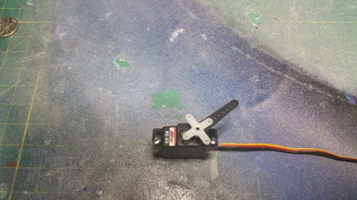
The new arm is much longer which will allow a much longer arc of movement. which will be needed to fully open and close the panels.
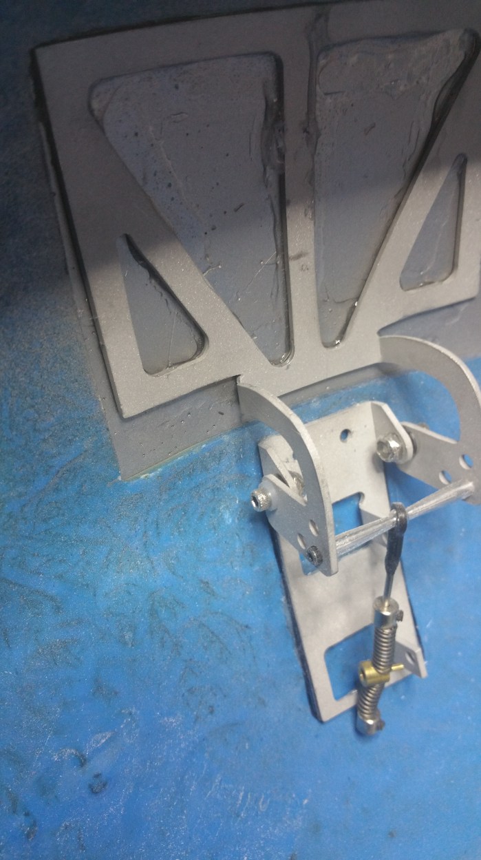
This is the hinge closed. The brass part is the pin that will be inserted into the servo arm. notice that it is right near the lower servo mount point.
This is the same hinge opened. Notice the pin has raised just about 2/3 of the way to the top servo mounting point. That’s about 3/4 of an inch. The small arm just does not have the length to travel that far.

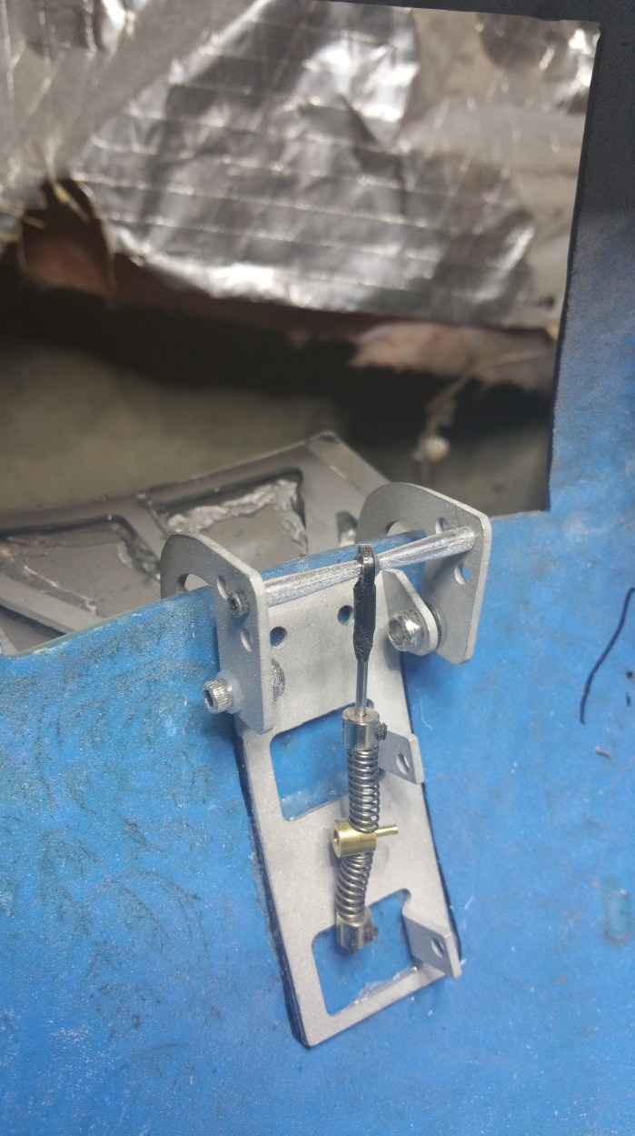
Here the servo is mounted into the hinge.
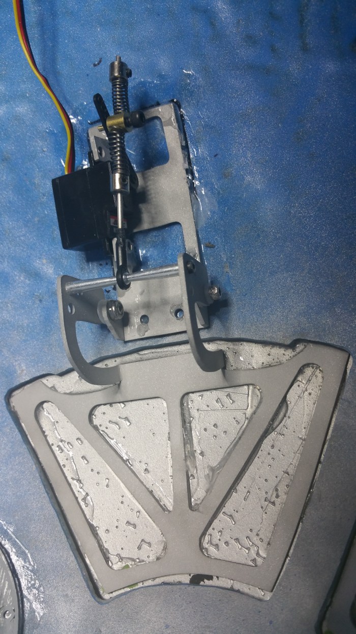
The hinge arm is connected to the servo arm in the closed position.

This is the same hinge now in the open position.Notice that the pin on this one, when the hinge is open, is right at the servo mounting point. You’ll also noticed that I removed the springs from the hinge arm. I did this because it allows greater flexibility on where exactly I can put the pin on the servo arm. When the springs were on i was limited, and because of that when the panels opened, the hinge would be completely open before the servo finished moving. The servo kept trying to get the arm into the correct position, but since it couldn’t it would sit and there making a jittering noise that was pretty loud. Especially when 7 or 8 of the servos were doing it.

All the servos hooked up to the MarcDuino. This is not the final mounting point for it. I’m not sure exactly yet were I am going to mount it.

But wait, no lights?

After some searching, I finally figured out the problem.

It turns out the power supply that I have been using just will not cut it anymore. The main problem is amperage. It turns out that the servos use up a lot of amps. If you look at the power supply during the video of the panels opening you can see the amperage (top number) being used range from about 1.5 amps to just under 2 amps. Apparently that pretty much tops out my power supply, so there is not enough current to run the lights and the panels at the same time. This, is not optimal. I had to get a new power supply.
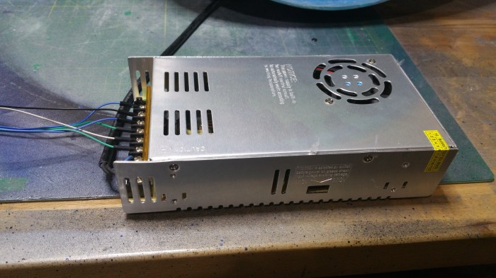
I found this, its a 12 volt 30 amp power supply. Powered by normal 110v ac house voltage. Should be plenty.
I knew that any sound system would also run off of 12 volts. But I wasn’t going to worry about getting it up and going until much later, when I was building the body. Because that is where the bulk of the components will be located. But since I would now have enough power I figured I would get i going a little earlier than expected.
The first component is an MP3 board
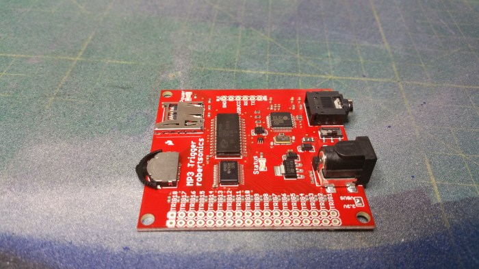
It’s really just an mp3 player.

I just needed to solder in some connectors and supply the mp3’s on a sd card. It outputs to a standard 3.5mm headphone jack. But it does not have an amplifier, so by itself it can only output to a set of headphones, again, not ideal. So the next thing to get was an amplifier.
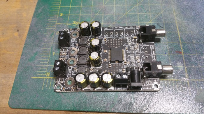
This is a 2 channel 15 watt amplifier, It’s the piece that will need the 12 volts. However it does not have a 3.5mm headphone input. It has RCA jack inputs. I couldn’t find an amplifier that fit my requirements that also has a headphone jack input.
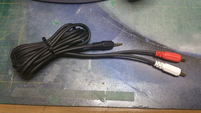
I need to get a shorter cable, but this one will do for now.

To prevent any motor or electronic “noise” coming through the speakers It was also suggested that I get this. A ground loop noise isolator.
Ok, as of right now I need three power circuits in my dome. One for the servos, one for the lighting and one for the sound system. “Luckily”, that’s exactly how many 12 volt circuits I can get off the new power supply. The only problem is, besides the amplifier, everything runs off of 5 volts. That’s where these come in.
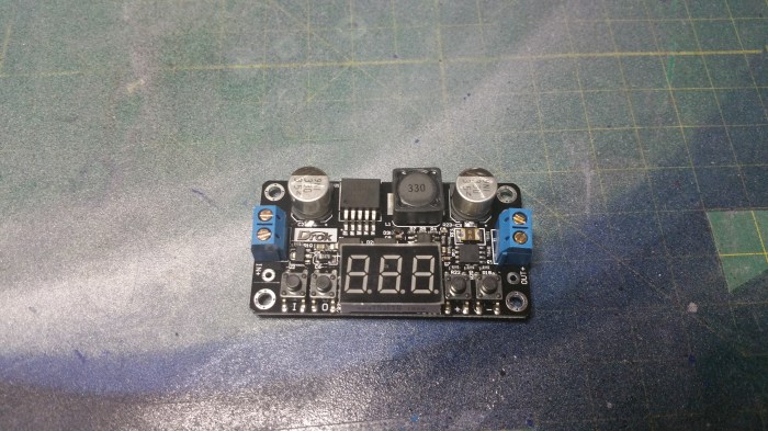
This is a DC Buck converter. It will step down any voltage from 35-5 volts down to 33-to 0 volts. It also has a display informing you of input and output voltages.

This is my audio circuit. Power comes in as 12 volts to the black bus bar. From there I take one circuit (grey & purple wire) off at 12 volts straight to the amplifier. I have another 12 volt circuit(orange and yellow wire) that goes into the power converter. You can see that it is set to output 5 volts. That powers the mp3 board(red and brown wires).
The mp3 signal comes out of the mp3 board, through the ground loop isolator, through the 3.5mm to rca adapter to the amp. And then the amp sends the signals to the speakers.
Whew!
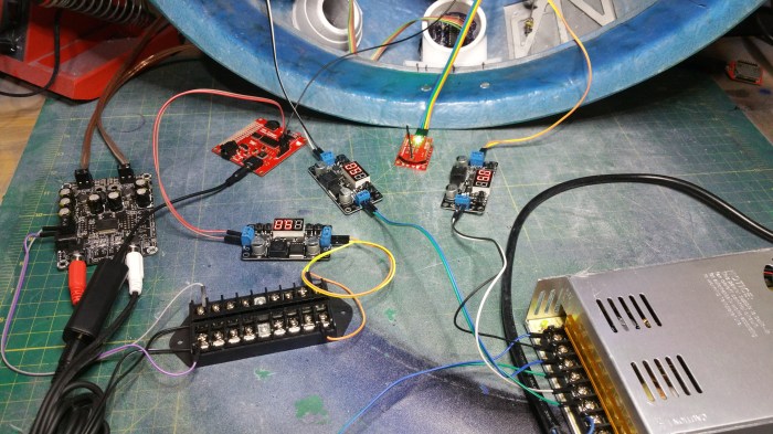
Here is the rest of the set up. Basically I pull two more 12 volt power circuits and put them into the power converts, with one feeding the lights and one feeding the servo’s. luckily I won’t have to find a place in the dome for all of this. most, if not all of the audio will be put into the body. I will also have to replace the 110v power supply with rechargeable batteries, which also goes into the body.

All of that feeds into the the MarcDuino. The black cable it coming from the Mp3 board. The rainbow colored cable is coming from Wifi antenna. The yellow/orange cable is the power for the MarcDuino/servos. The Black/Red/Yellow cables feed all the individual servos.
I have already resigned myself into making custom length cables to help clean this mess up. But that will be for another day.
For this day I have this
And this
He will sit there and do this until you shut him off. Just random R2 noises. I love it.
So, what is next? To tell the truth I’m not sure. I want to put lights and servos on the holoprojectors, but that may require me to replace my current ones, and I’m not sure if I want to do that yet. If I can figure out a way to keep them then I will do that next. If I can’t then I guess I will start in on the body. But I probably won’t start in on the body no matter what happens until at least late June early July. There is a convention of droid builders coming up in the middle of June called DroidCon 4. They only have these every two years and I’m going to this one. So I won’t start anything major until after that.
