Shortly after starting my build I discovered that there were a lot of parts that could be 3D printed. I even ordered a few. They weren’t too expensive. I started adding up in my head how much it would cost, based on the parts that were available, and I quickly realized that it would add up pretty quick. I knew that you could get a relatively cheap printer, but I didn’t know how cheap. So I started doing some investigations. It was about this time Tina and I went to the National Maker Faire.
Makers Faire bills itself as “The Greatest Show (and Tell) on earth—a family-friendly festival of invention, creativity and resourcefulness, and a celebration of the Maker movement.” It was basically a showcase for any one that builds, anything. Toys, nick-knacks, prosthetic limbs, cars, and just about anything in between. It had Individuals, schools, clubs, corporations all presenting things that they made, tools, techniques, and demonstrations. We had a pretty good time.

A 3D printed car

A paper T-Rex that someone was walking around in(Tina for scale)
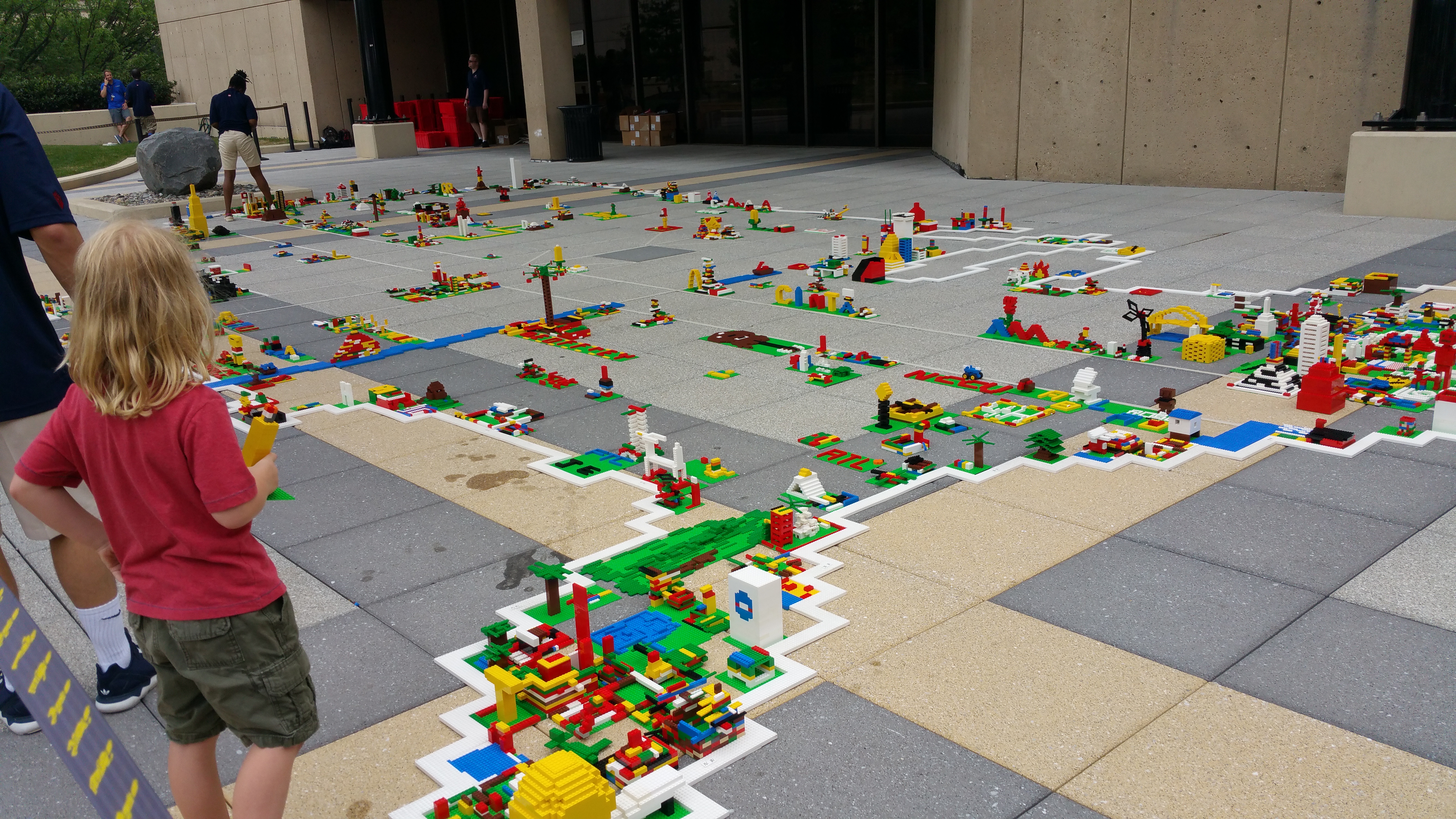
Lego!

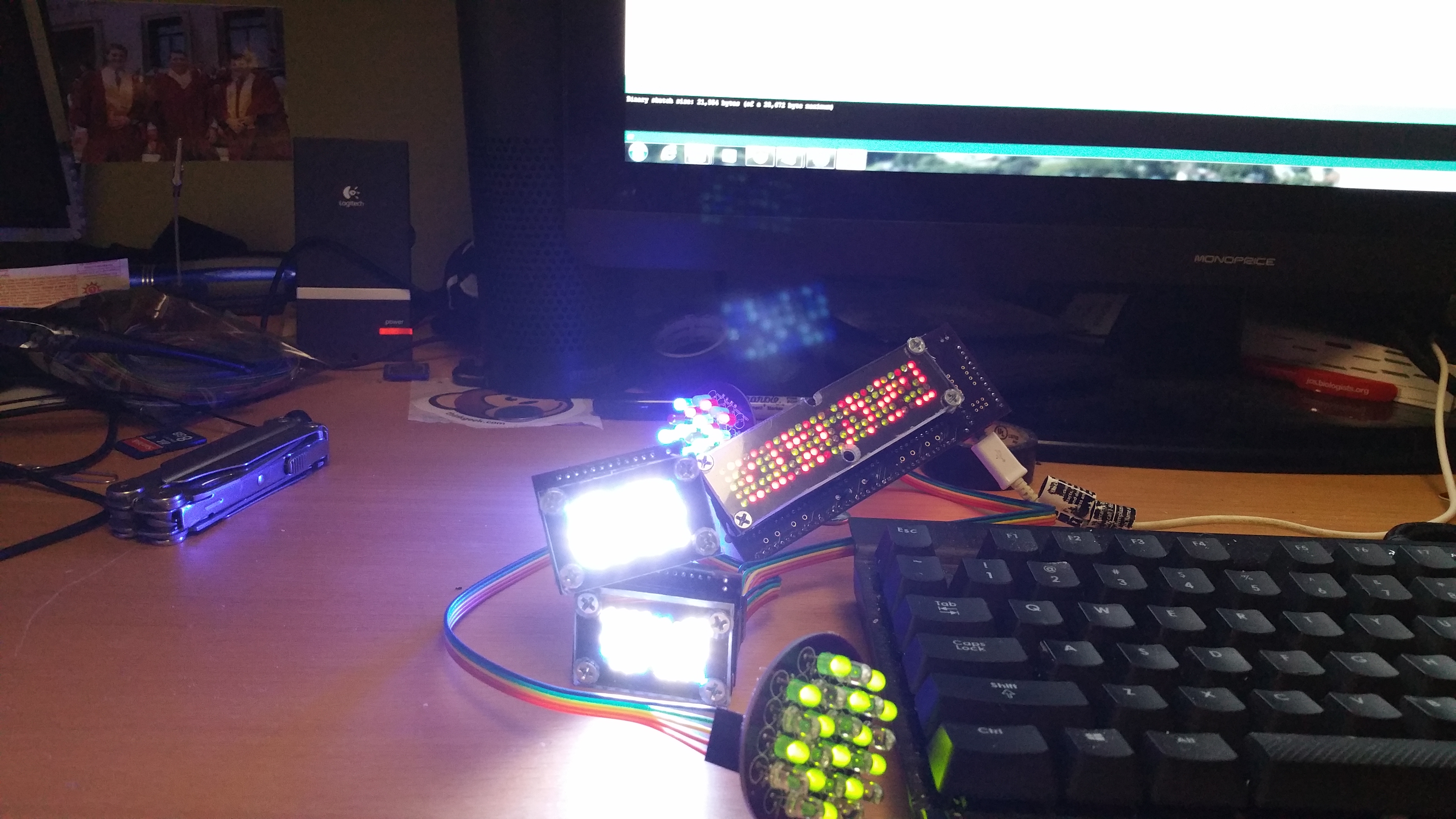
Robots!

A wooden robot that Tina and I both purchased for ourselves. (she still hasn’t built hers)
One thing that i noticed, about 80% -90% of the booths had something to do with 3D printing. It is pretty astonishing what can and is being printed. It definitely got both our attentions. All of this and the fact that it would probably pay for itself, if I could print the parts that I needed instead of buying them from someone else. It was decided that we would get a 3D printer.
There are many different types of printers, that use different process for laying material down, or in some cases build material up, to form whatever shape is needed. The process that is most popular in the consumer grade printers is Fused Filament Fabrication (FFF). Basically a spool of material, usually plastic, is feed into an extruder that melts the plastic and deposits it on the work surface to form layers of material. The extruder, and/or the work surface, is moved in all three axis’s (X,Y,Z) by motors, which allow the layers to be laid on top of each other in any direction, thereby building a 3D object.
There are a few ways that you can buy a 3D printer. One is go to the store. Home Depot, Best Buy, even Walmart has some printers. Buy one off the shelf, take it home, and be printing within a couple of hours. This requires very little knowledge about 3D printing, but it is expensive. Another way, is to do exhaustive research and buy each individual piece and part yourself, and build it yourself. This requires a lot of knowledge about 3D printing, but it is probably the cheapest way to go. I went for the third option.
I found a company online that sells a 3D printer kit that you assemble yourself. This is a popular choice for people who really want to learn everything about 3D Printing. I decided on what is called a Prusa i3 printer. It is completely open source on both the hardware and software. Basically meaning that anyone is fee to modify either the hardware or software configuration. It also usually means there is a large community of people willing to help, if you get stuck and can’t figure out something.
It arrived on Thursday

Not as big as I was expecting, but it was kind of heavy
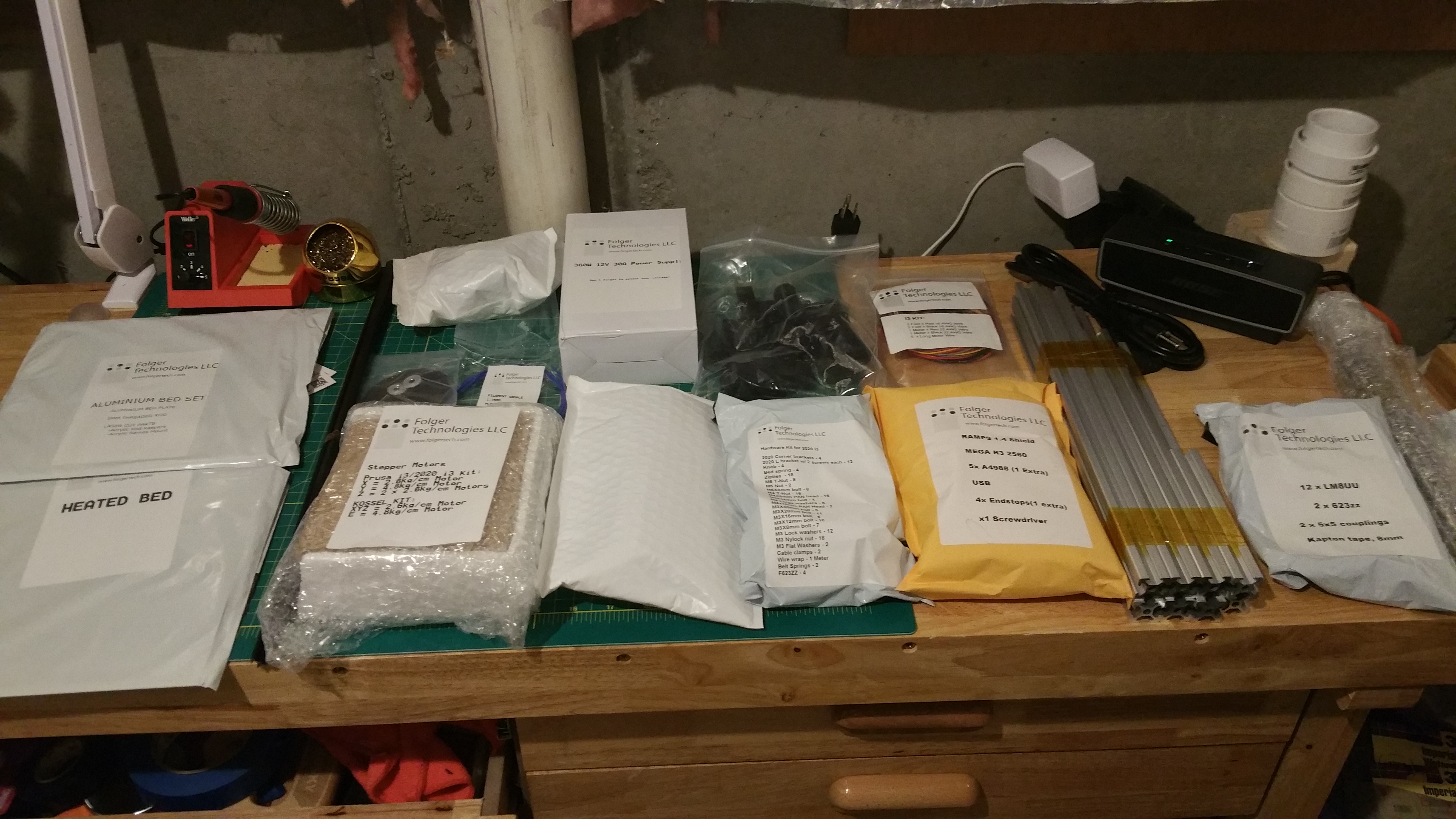
Unboxed, or, as Tina put it, a 3D printier in 2D form

Most of the parts laid out
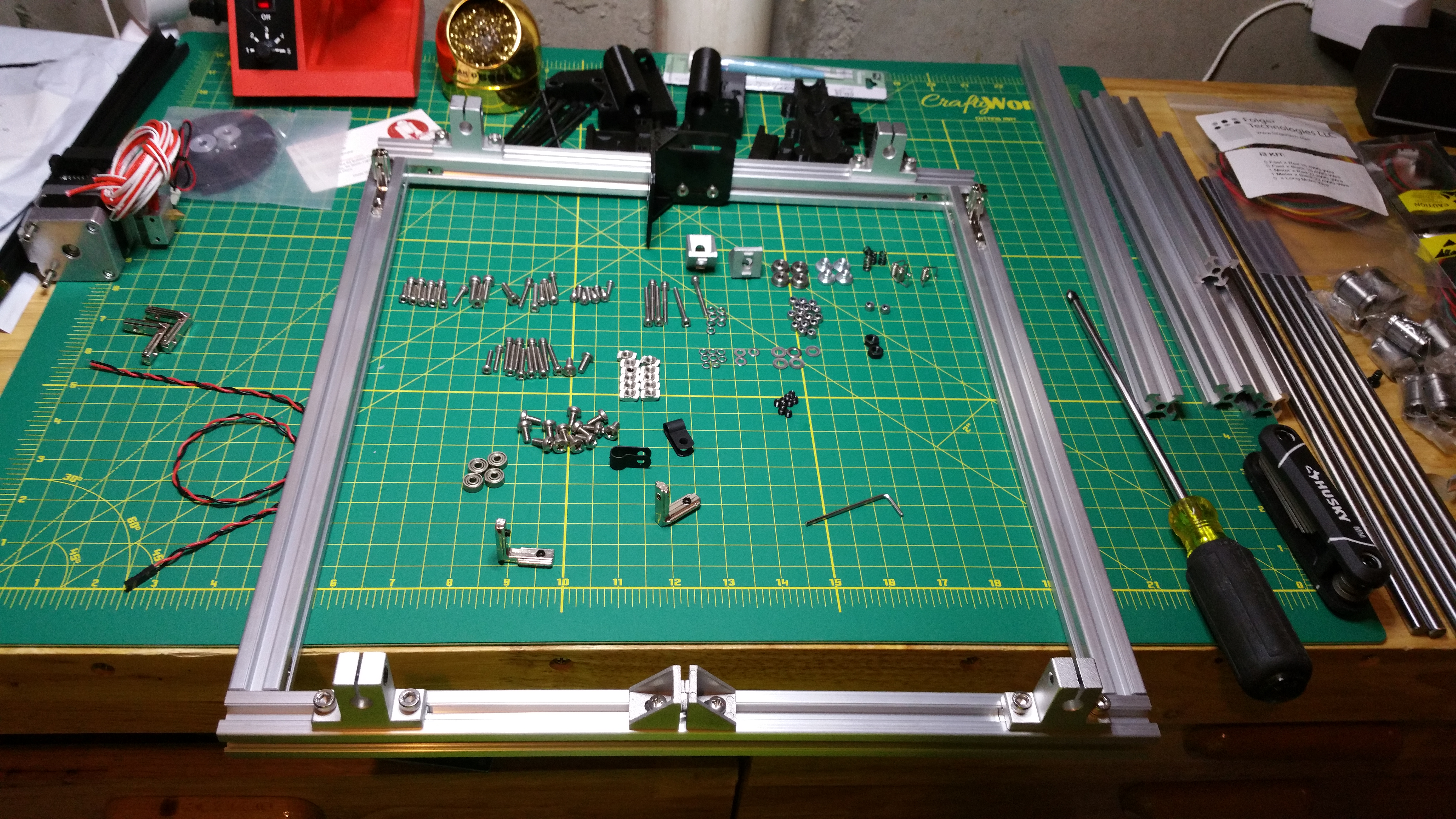
Main Frame, Every thing will be built on top off this. The closest side is the front.

These are the rods that the print bed will travel back and forth on. This will be the Y axis (front to back)

Vertical support, This will be the Z axis (up and down). Also notice that I had one too many bearings on the Y axis rods, I had to take one off.
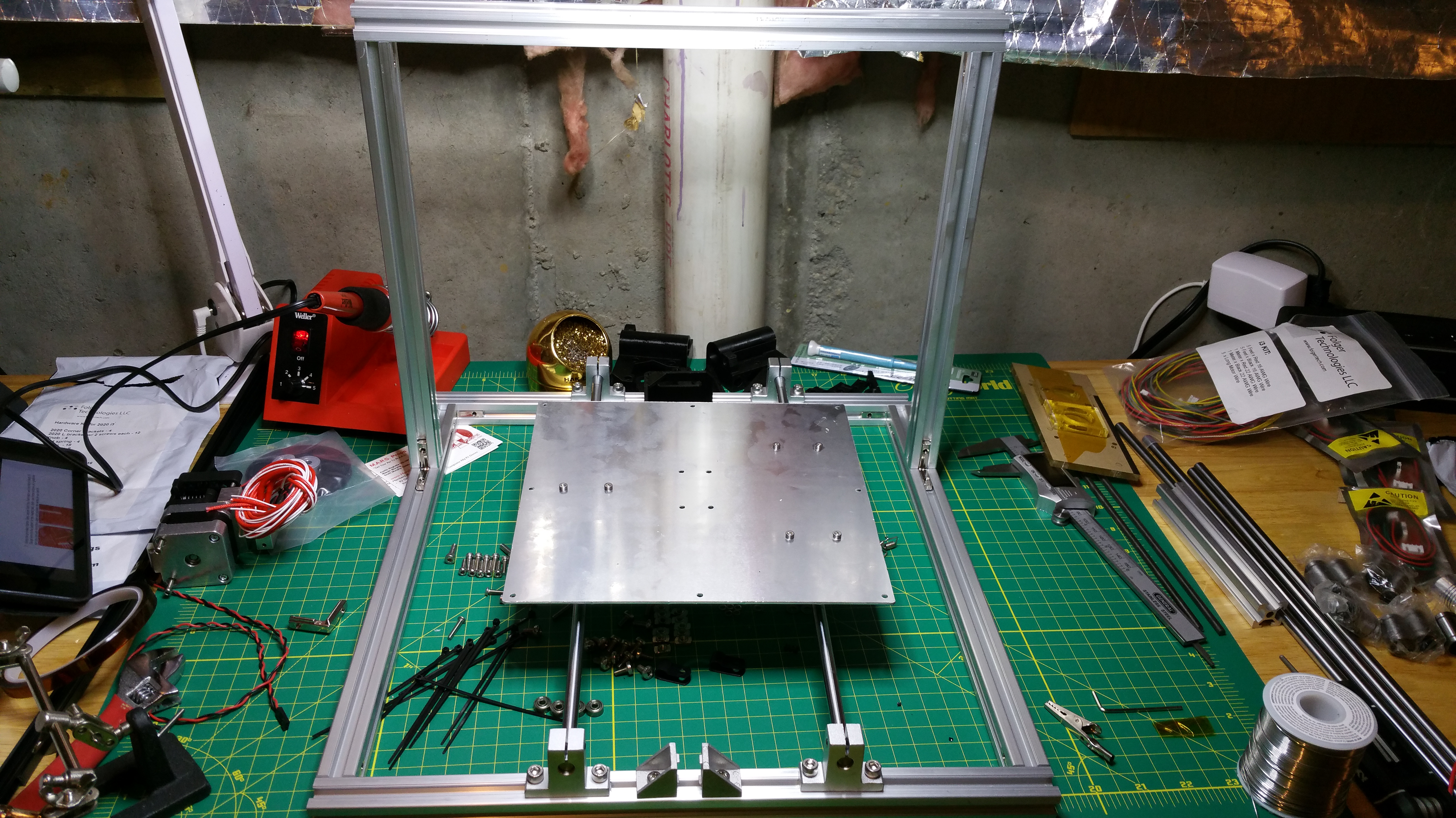
support bed

Wiring up the heated print bed. For some plastics, especially ABS plastic, you need a heated bed to keep the first couple of layers of your print from warping.
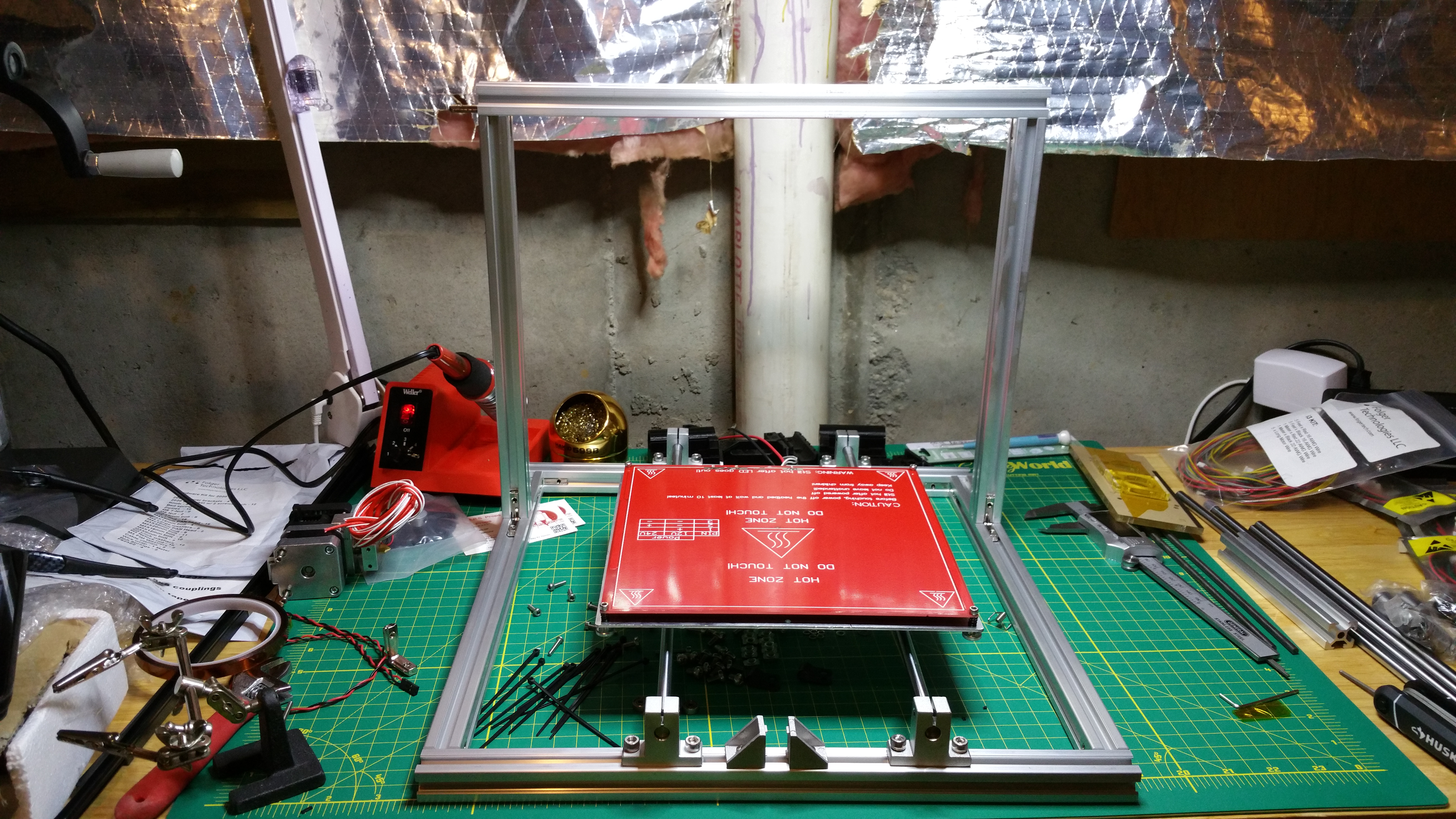
Heated bed is now mounted to the support bed. You could print directly on this but most people don’t. Usually a piece of glass is put on top to make sure you have a completely flat bed to work off of.

Attaching the Z axis motors.

Building the extruder carriage. This will also be the X axis (left and right)

Mounting the extruder

These are the guide rods and the threaded rod. The Z axis motors will attach to the threaded rods.
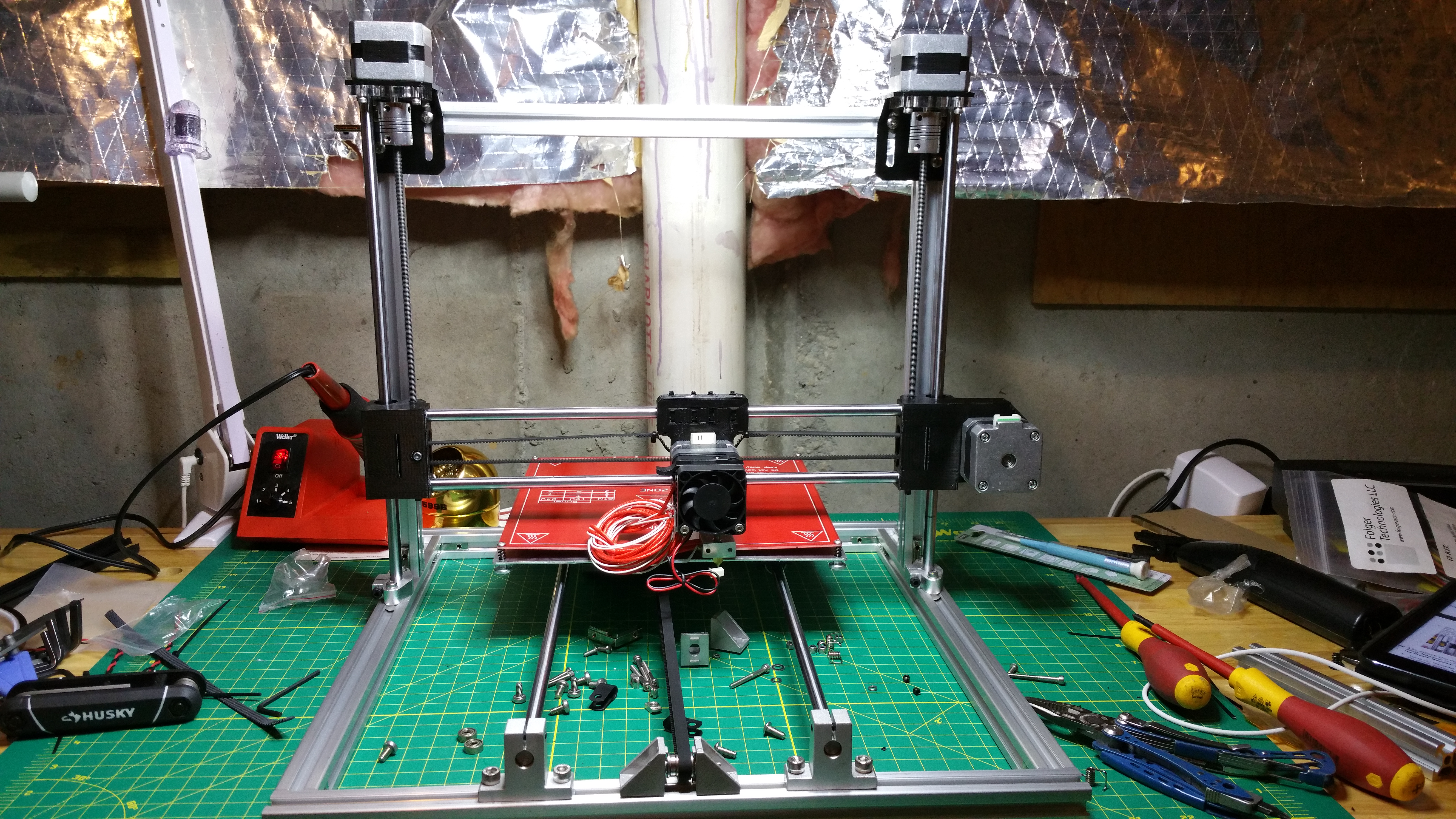
Installing the X axis assembly onto the frame. The motors will turn the threaded rod, making the assemble move up and down on the guide rods.
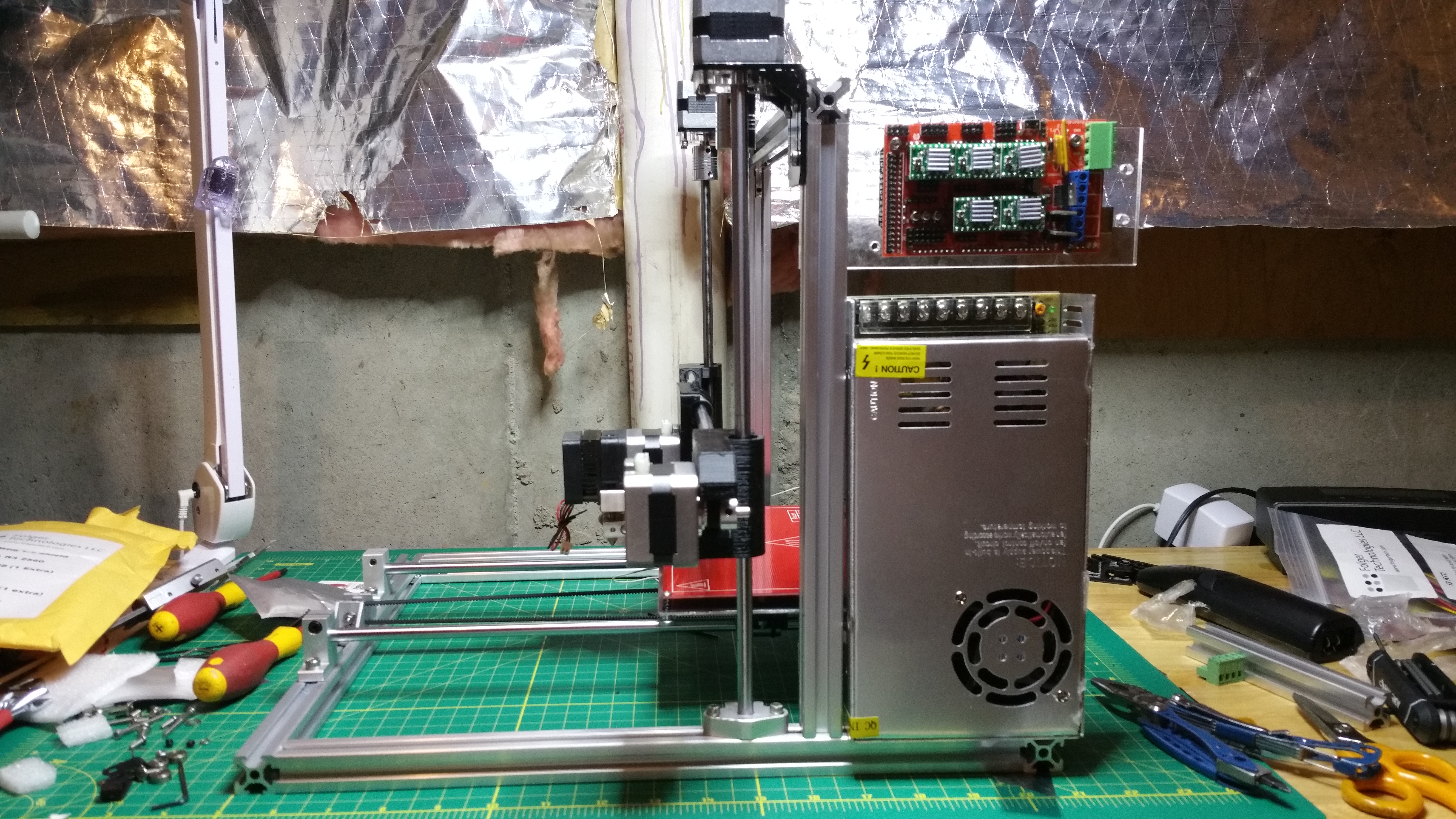
Attaching the power supply and control board, thankfully I didn’t have to solder anything on this project.

A little bit closer view

Oh God, the wiring
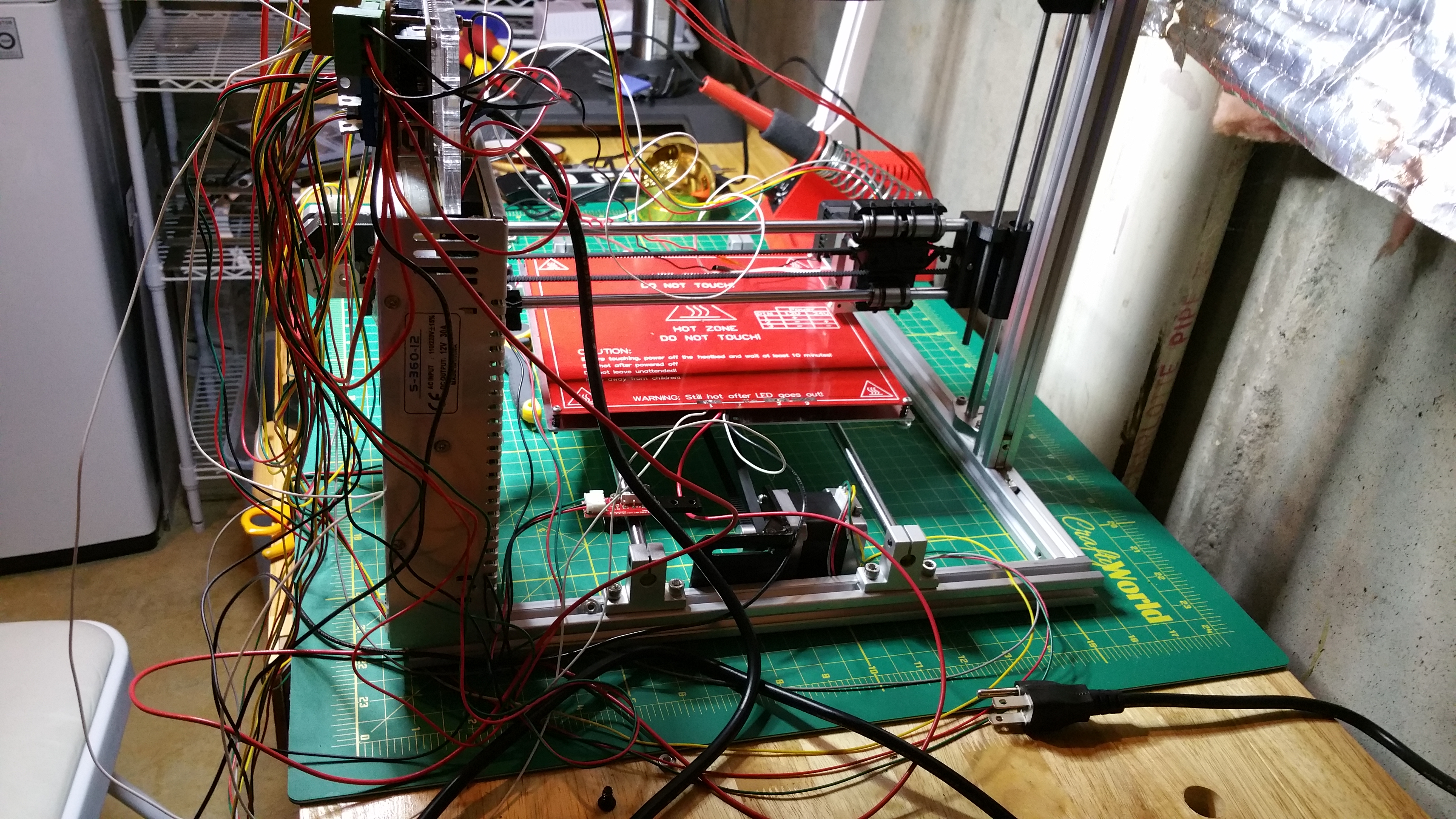
It even wraps around the back.

That’s much better

I wasn’t able to hide all the wires. Some have to have slack so they can move with the extruder.

Built
I am in the process of setting up the software. It is proven to be one the trickier parts. It doesn’t help that I think I have a bad controller board. I already talked to the company and they are sending out a replacement. That’s were I am right now. It took me about 10 15 hours to assemble it and I have spent 4 or 5 hours trying to get the software to work properly. but hopefully most of that was the bad controller.
In the middle of all that (Saturday morning to be exact) I got a surprise on our porch.

Hmm what could it be? (yes know its already opened.)

IT’S THE DOME!!!!!

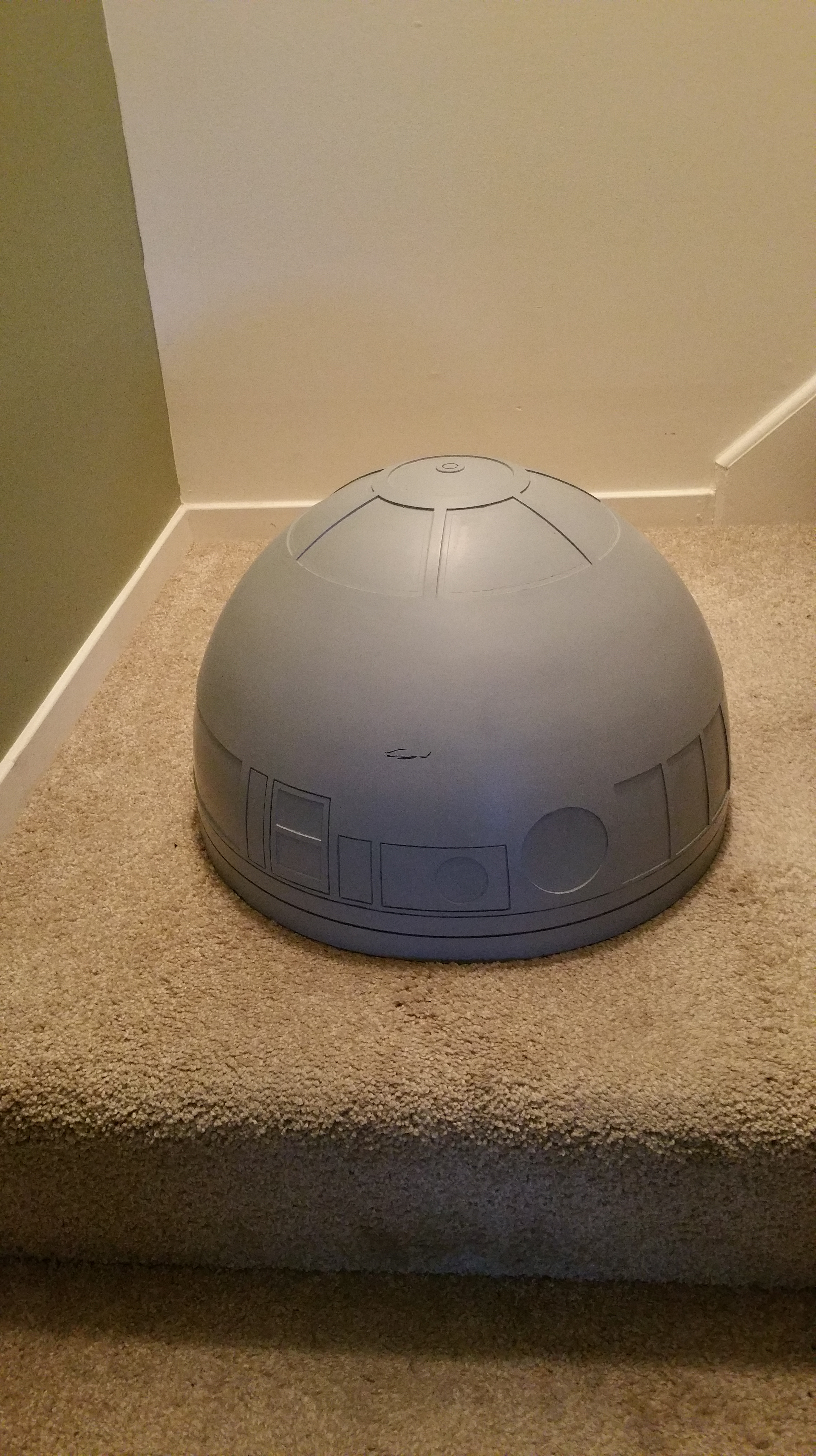
Its a composite dome, a composite of what, I don’t know. But it’s light, less than 4 lbs

The people that make it sign it and put a quote from the movie that they were watching while it was being made.
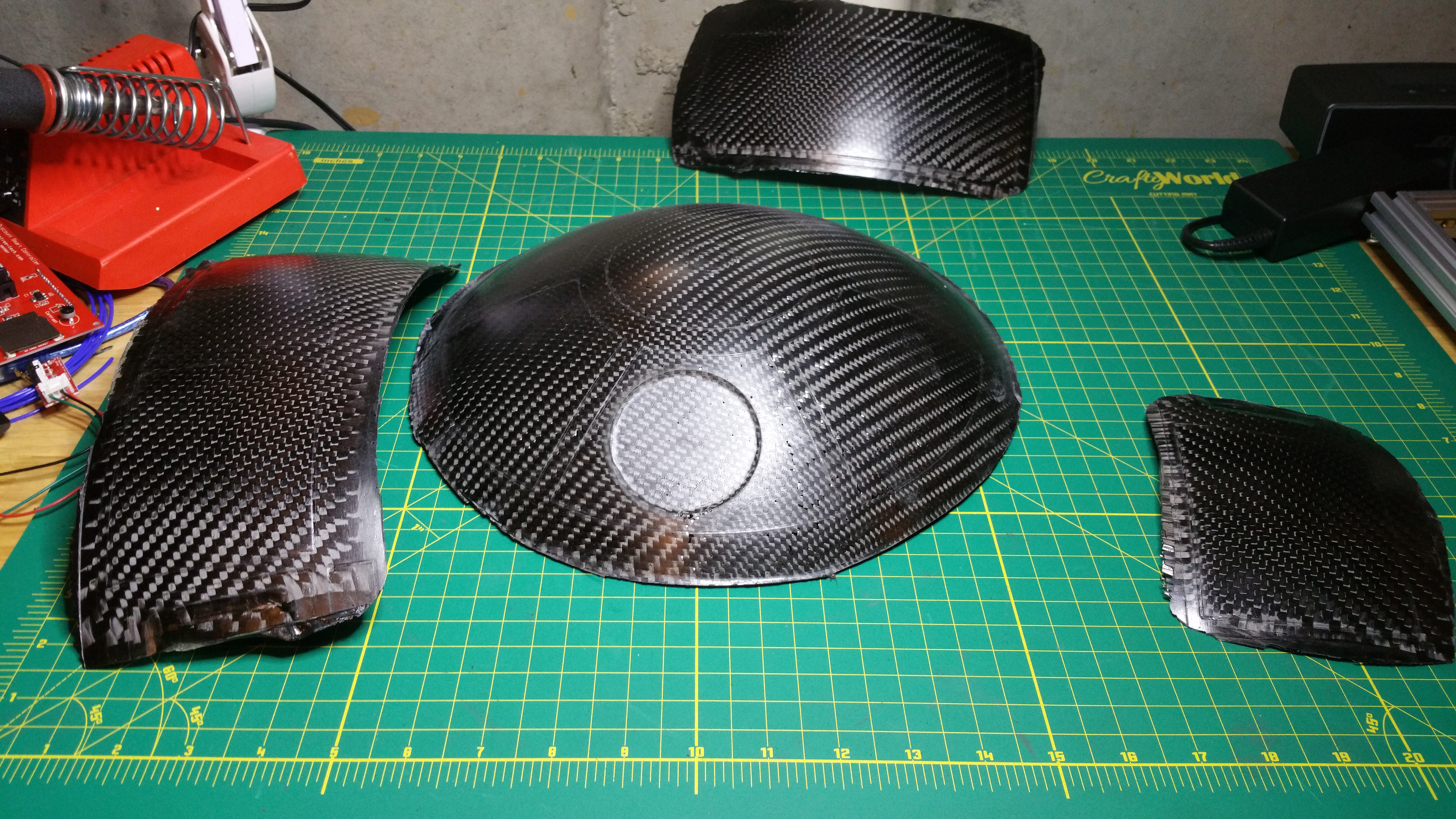
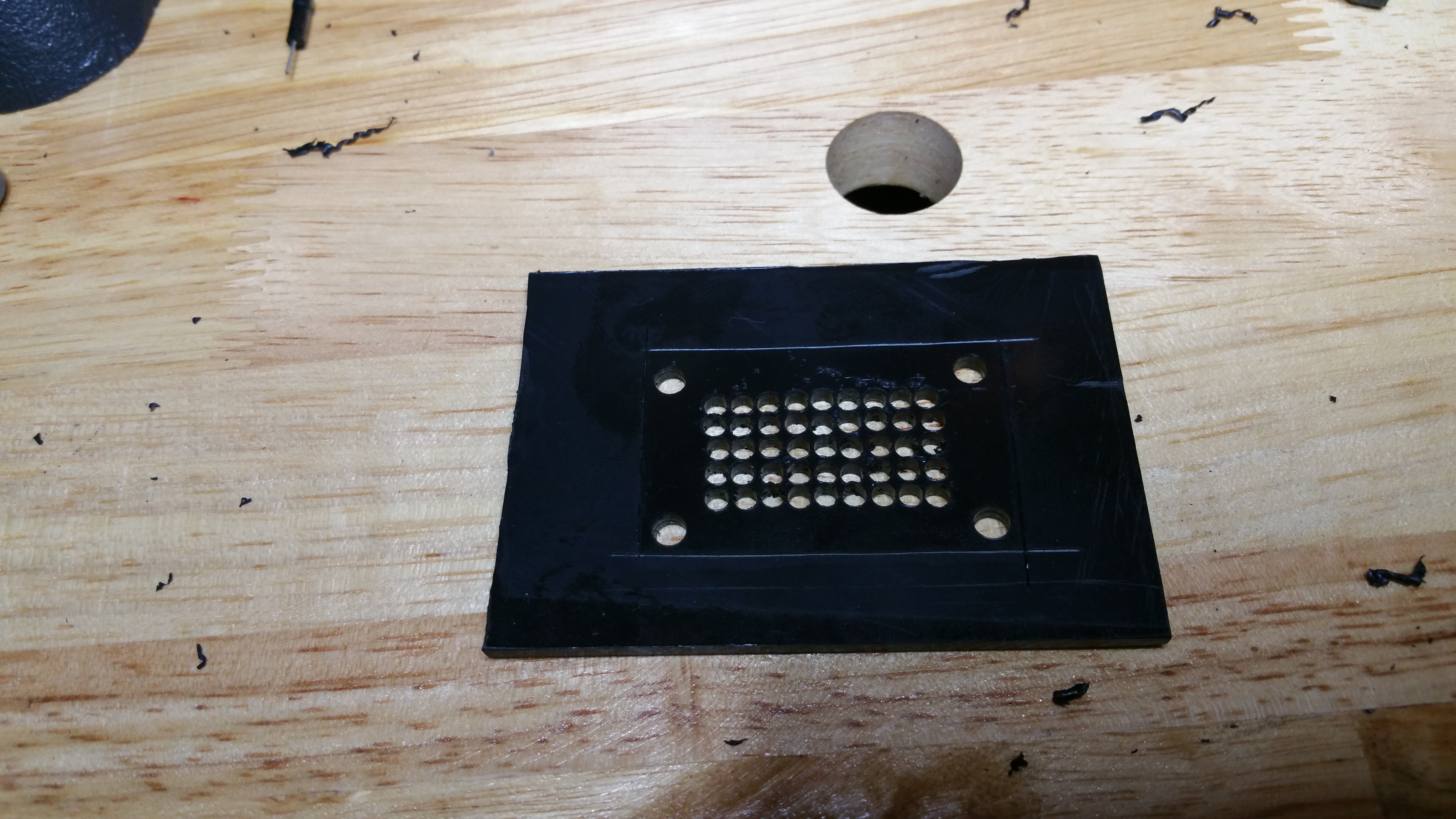
It also came with these. These are carbon fiber panels that I will cut out paint and put on the dome. These will serve as “doors” that open on the dome that I will be able to control with servo motors.

Safety first, especially when cutting fiberglass/carbon fiber with a Dremmel rotary tool

First panel cut out

Test fit on dome

I screwed up (just a little, fixable) on the second piece I cut out because I lost the cut line. I outlined where i need to cut on the rest.
That is it for now. I’m not sure how often I will put out an update, They should be a little bit more often, especially now with both the printer and the dome finally arriving.